

Help wiring relay
 Ragtop
Posts: 406
Ragtop
Posts: 406
I am getting some relays:
"Description: These are high quality Single Pole - Double Throw (SPDT) sealed relays. Use them to switch high voltage, and/or high current devices.
This relay's coil is rated up to 12V, with a minimum switching voltage of 5V. The contacts are rated up to 5A (@250VAC, 30VDC)."
I have no clue how to wire a relay, and thought I would ask before burning the house down. I want to use it to control Halloween stuff off a 12v battery.
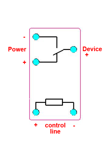
I have included picture of how I was thinking they work. How far off base am I?
"Description: These are high quality Single Pole - Double Throw (SPDT) sealed relays. Use them to switch high voltage, and/or high current devices.
This relay's coil is rated up to 12V, with a minimum switching voltage of 5V. The contacts are rated up to 5A (@250VAC, 30VDC)."
I have no clue how to wire a relay, and thought I would ask before burning the house down. I want to use it to control Halloween stuff off a 12v battery.
I have included picture of how I was thinking they work. How far off base am I?
360 x 480 - 65K
Comments
The coil is the focus of a design solution. Often a 2N2222 transistor is all you need to turn on the relay as the coil usually requires less than 500ma.
But the other question is whether it is a 5 volt, 12 volt or 24 DC volt rated coil. (There are also 120 and 240 VAC rated coils, but you can't use those with a micro controller.
I suppose you want an all 5 volt set up, but that is often not as easy to get powerful replaceable relays (they do wear out) as with 12VDC.
Enclosed is a basic diagram. 5 volts drives the base of the transistor (a 2n2222) and 12 volts is the rated relay. (ignore the Vin =+12, it is Vin =+5) The resistor between the micro-controller and the base should be about 330 ohms (to protect the micro-controller).
http://www.sparkfun.com/datasheets/Components/General/JZC-11F-05VDC-1Z%20EN.pdf
The red text is what I added to the picture. I need to know what goes to which of the relay's 5 pins. I figured I would need a transistor to send 5v signal to relay, but the relay doesn't need a ground to the microcomputer?
Picture of relay is here:
http://www.sparkfun.com/commerce/product_info.php?products_id=100
That one looks like the positive 5v and 12v are being feed into
the ends of the magnetic coil. and both being grounded via the diode to
the 12v line.
And it looks like there is three outputs. That would be 6 pins?
You don't tell how you want to control the stuff, if you are not using any kind of microcontroller you won't need any relays. Just a simple switch.
The electric part which turns on the switch is called the coil. Just think of that as you would a light bulb. It has two connections just like a light bulb.
And then separate the switch part. Just think of that as a switch.
The only thing you need to be concerned with is amperage or mA. That should not exceed what the pin on the chip can provide.
Then a coil, when electricity is removed, will spark! Just like a coil in a car...
...So you need to protect the chip from that spark by placing a diode backwards on the two coil connections. This causes the spark to "short" when electricity is removed from the coil and thus the electricity does not travel into the chip and damage it. But by placing the diode "backwards" on the coil connections, this allows the power from the chip to operate the relay without "shorting".
More...
http://www.physics.unlv.edu/~bill/PHYS483/relay.pdf
like a simple question that isn't getting a simple response. If someone could please reference the diagram that I
provided from the manufacturer's data sheet which failed to say which pin is for what. The red print is what
I added as a guess to what the pins go to.
Ok, I tried to make a simple diagram for you here, does it make things more clear you think?
I still don't understand why the 5v circuit seems to be connected to the 12v circuit. I thought the whole point of the relay was too keep those two circuits physically separated.
And is the diode a separate component from the relay?
Your relay is really a 12 volt coil device. The reference to 5 volts just confused the issue. That rating is provided to show that even if the 12 volts dropped to about 5 volts, the relay would still operate.
Its important if you're designing with the possibility of the battery being cold or partially discharged or otherwise unable to keep the voltage up at 12 volts, but in this case, its not too significant.
You will have to learn something about how transistors work.
The 5 volts input has it's current amplified up to 200 times and the +12v side provides the extra current as well as the higher voltage the coil requires.
One way of looking at the inside of a transistor is as two diodes. The electricity from the +5 goes to ground and the electricity from the +12 goes to ground (if you build the circuit right). So the transistor does the work while the micro-controller provides a low current and low voltage to do the control.
@Moskog - Thanks for clearing up the details.
I included a new diagram of the relay. Is this looking correct?
I assume I could use the empty pin to turn something on/off opposite of the state of the other pin.
I think I see what you are asking!
You know there are two pins which connect to the relay coil, but are asking which of those 2 pins would go to + and which to -?
Does not matter! Any one can go to + and the other to -.
Or are you asking of all the pins on the bottom of the relay, which 2 go to the coil? That would be the two pins furthest away from the center pin.
Feel free to keep asking questions if you don't understand something.
When turning on the Microcontroller the transistor will go On and the relay switch will open your connection and the Halloween will be shut off. I would recommend you connect the Halloween to the Normally Open pin leaving it Off when relay is turned off and On when relay is active. In your diagram you put the + Halloween to the left upper pin on your relay instead of the left lower.
I had this completely wrong in my head as I thought the 5v powered the coil closing the plate to complete the 12v circuit.
But now I am wondering why the relay is needed? If the transistor is what is actually protecting the microcomputer from the 12v.
The starter motor in a car takes a LOT of electricity (amperage) to power it. Notice the very large wires which go to this motor.
But there is no way on earth you could run those big wires up the steering column to the key switch!
So instead they use a small amount of electricity (amperage) to operate the key switch and run the wires from that to the starter motor.
Then inside the starter motor is a relay (solenoid - same thing). The small amount of electricity makes the relay "turn the switch" and this connects the large wires to the starter motor.
So small amount of electricity (small amperage) = small wires.
Large amount of electricity (large amperage) = big wires.
And that is what you would use a relay for. To switch on/off a large amount of electricity with a small amount of electricity.
And inside a microcontroller are tiny wires which will not carry much electricity. There is a limit. So if you are turning on something which uses a lot of electricity, you need to use something like a relay to switch it on/off.
And just the coil of a relay might use more electricity than the microcontroller can handle, so you use a transistor - which is a switch too - to power the coil of the relay.
But that transistor might not be able to handle the amount of electricity the contacts of a relay could.
Transistors tend to be sensitive and will burn out.
Relays are quite strong and can take a beating!
Video
http://www.facebook.com/video/video.php?v=10150095187710550
http://www.facebook.com/video/video.php?v=501052195549
I too love building homebrew things on a bit of wood.
I will consider writing it up when it is finished.