

Are these the correct connects for Prop to 4.3" Breakout board???
 Harley
Posts: 997
Harley
Posts: 997
Some where in time I got this info on the 4.3" Breakout board. And also I had a notation on that printout that a swap on pins 7 and 8 (PCLK and DE), and that 17 and 18 could be tied together. Has anyone found this correct?
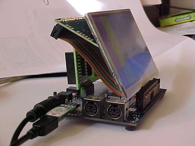
I've added a 2x20 header on a Prop ProtoBoard and one also on the Breakout board and use a 40-conductor ribbon cable with female sockets on each end. However, to have the display right side up, One socket is on one side of cable and one on the opposite side. Continuity checks out. However I just get pretty vertical colored lines or bars. And some times if I touch a particular conductor or pin I almost can read the words 'graphics demo' at the screen top. I've tried swapping those pins but that doesn't help any.
The attachment hopefully shows my 'stackup', letting the SD card board sort of support the cable, LCD and breakout board, temporarily. Colorful screen, but not correct!
I just noticed if I touch the LCD metal, on sides or back, the display seems to lose sync, at least the colors and 'bars' begin to 'run' scrambled
Propeller / 4.3 breakout board i/f for 4.3" Samsung color LCD module - 7 Jan.2010
GND 1 GND
A29 2 SDA (I2C)
A28 3 SCL "
GND 4 GND
3.3V 5 Vdd
A27 6 IRQ
*A26 7 PCLK * these two s/b swapped
*A25 8 DE
A23 9 R1 msb
A22 10 R0 |
A21 11 G1 |
A20 12 G0 (byte)
A19 13 B1 |
A18 14 B0 |
A17 15 HSync |
A16 16 VSync lsb
A24 17 DON (DON/BL = 1 for ON)
A24 18 BL
GND 19 GND (for backlight)
+5V 20 VBL
Prop H1 pin J1 Breakout board
I've added a 2x20 header on a Prop ProtoBoard and one also on the Breakout board and use a 40-conductor ribbon cable with female sockets on each end. However, to have the display right side up, One socket is on one side of cable and one on the opposite side. Continuity checks out. However I just get pretty vertical colored lines or bars. And some times if I touch a particular conductor or pin I almost can read the words 'graphics demo' at the screen top. I've tried swapping those pins but that doesn't help any.
The attachment hopefully shows my 'stackup', letting the SD card board sort of support the cable, LCD and breakout board, temporarily. Colorful screen, but not correct!
I just noticed if I touch the LCD metal, on sides or back, the display seems to lose sync, at least the colors and 'bars' begin to 'run' scrambled
640 x 480 - 26K
Comments
Make sure you've set the pins in the driver to be the same as the ones you're using.
Thus DE, breakout pin 8, wasn't connected in the source to the proper Prop pin and was floating. That then explained why that one pin only could be touched and affect the display patterns/colors. Works as expected now for the PSB Graphics and Paint Demos. Phew!
Getting past that hurdle was where I expected problems, as it was up to me to get everything wired and driven properly. Not easy like conneccting the 3.5" LCD to the PTP board!! They both, 3.5 and 4.3" displays are just super displays. Thanks for all the need for help getting this 4.3" guy working.
Just thought I'd show this Prop ProtoBoard setup with the 4.3" LCD. A SD card board is accessed from the other end and sort of supports the LCD/breakout board/cable. The SD is not operational yet. Has anyone have the 4.3" LCD and SD card working? If so, what object is used for SD?