Shop OBEX P1 Docs P2 Docs Learn Events
OUTL and DIRL — Parallax Forums

OUTL and DIRL

Speaker337Speaker337 Posts: 14
edited 2010-09-09 06:07 in BASIC Stamp
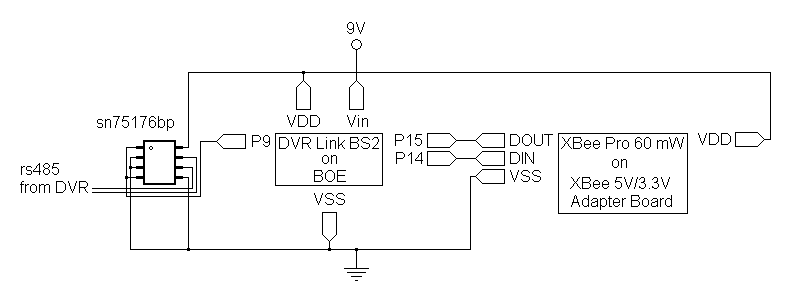
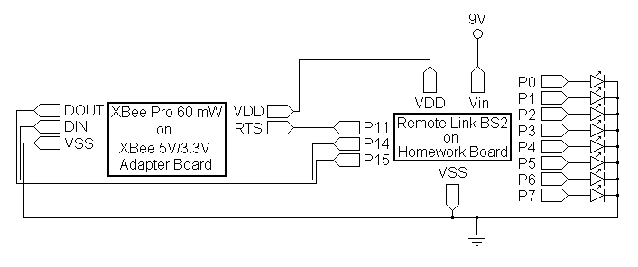
I am trying to set up a mobile platform that can be controlled from a DVR using PTZ codes. There are three boards. The first board takes codes from the DVR and condenses the info to a single byte and sends it out via radio. The second board will be used for all sensors on the mobile platform. Currently it is only handling the radio receiver. The third board handles the driving of the mobile platform. I am having a difficulty with the second board. When I try to use pins 0 - 7 for output it fails. As long as I use debugs to monitor what is happening, everything works flawlessly. When I try to use pins as output, the second board fails within a minute. By fail, I mean that it clears, and then doesn't show anything else. The program called remote_side has two lines near the bottom that are OUTL and DIRL. If I comment these two lines out it works great, but as soon as I make those two lines active, it fails. I guess I can use a serial connection between boards two and three rather than 8 lines in parallel. That is what I will try next, but I am still very curious about why those two lines of code cause it to fail. Any ideas?

Comments

  • Mike GreenMike Green Posts: 23,101
    edited 2010-09-08 08:45
    From your circuit diagram (if it's correct), you have 8 LEDs connected to Stamp I/O pins without any current limiting resistors. When you set any of the OUTL bits to one, you're essentially short-circuiting that I/O pin to ground. In addition to possibly damaging the I/O pin, that current surge may cause the supply voltage to drop momentarily to where the Stamp resets. I suggest using a resistor in series with each LED on the order of 560 Ohms (or higher). That would limit the current through each LED to about 6mA and the total amount of current (should all 8 LEDs be on) of about 48mA. Each group of 8 I/O pins has its own current limits. Individual I/O pins can handle 25mA while each 8-pin group can handle up to 50mA.

    DIRL sets the direction of the I/O pins. If the I/O pin is in input mode, it can't short circuit.
  • Speaker337Speaker337 Posts: 14
    edited 2010-09-08 19:06
    Thanks, Mike. That bs2 is on a homework board. I was counting on the built-in 220 ohm resistors to limit current to a safe level. I will put in enough additional resistance to meet or exceed the 560 ohm you recommend.
  • Mike GreenMike Green Posts: 23,101
    edited 2010-09-08 19:36
    A 220 Ohm resistor with a red LED will allow 15mA. More than 3 LEDs lit at one time will exceed the maximum allowed current per 8-bit I/O port. More than 6 LEDs lit at one time will exceed the maximum total allowed current for the whole processor chip (PIC16F57).
  • Speaker337Speaker337 Posts: 14
    edited 2010-09-09 06:07
    Thanks, again, Mike. I just wired up the LEDs and it seems to be working reliably now.
Sign In or Register to comment.