

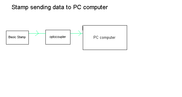
Question about isolating serial connection
 AJ-9000
Posts: 52
AJ-9000
Posts: 52
Are there any inexpensive optocouplers like a phototransister TIL-111 or a photodarlington TIL-119 that would work in a situation like sending data one way from a Stamp to a PC ?
Update;
I think I know the answer and that is that all serial communication uses alternating current so it wouldn't work using a simple optoisolator.
Update;
I think I know the answer and that is that all serial communication uses alternating current so it wouldn't work using a simple optoisolator.
633 x 338 - 7K
Comments
You can do what you show in the diagram with most PC's as they will interpret a signal close to 0v as a negative voltage and a signal in the 5v range as a positive signal. Use the TIL111 and drive the led side from the stamp(with appropriate resistor in series).
On the transistor side, pull the collector up to 5 volts through a 220 ohm resistor. To achieve isolation, the transistor side 5 volts would have to come from the PC. The serial signal appears at the collector-resistor junction and goes to rx on the PC. Emitter of course goes to 0 volts.
If you are running the stamp on batteries or an isolated power supply, the communication isolation is less important.
http://www.maxim-ic.com/products/protection/isolated/rs232.cfm
http://www.linear.com/pc/productDetail.jsp?navId=H0,C1,C1007,C1016,P90353
The output on pin 2 (PC's RxD) gets its negative supply voltage from the PC's TxD (pin 3) when the opto isn't conducting. When the BASIC Stamp output goes from high (mark) to low (space), the optotransistor will conduct. If there's a positive voltage on the PC's DTR (pin 4), pin 2 will go from negative to positive. For this to work, you have to make sure that DTR is asserted from the PC's side. In the BASIC Stamp's debug screen, for example, there's a checkbox for this. OTOH, if you're writing you own PC serial software, there will be an API call that you can use to make sure DTR is asserted.
The 5.6K resistor value is only a guess. You may need to adjust it for optimum performance. Also, when sending with the Stamp, use positive (true) serial communicaiton, since the opto is wired, in this case, as an inverter.
-Phil
I have a question, when Tom Sisk(stamptrol) recommends using a TIL111 he says "the transistor side 5 volts would have to come from the PC" and the schematic of Phil Pilgrim's doesn't show that wiring, was that accidently omitted ?
As you can see by the drawing below this project reqires a number of Stamps but at this time I only plan to use 8 initially. Assuming Phil's skematic is wrong and there should be a 5 volt wire going from the PC to the TIL111 that would create a problem because I would then have to power all of them at once. Is there another optocoupler available that doesn't require a 5 volt power supply that I could use in conjunction with one line conditioner near the PC to boost the voltage ?
Just about any phototransistor-output opto will work here. It doesn't have to be a TIL111. But you will have to experiment with the emitter resistor value to get the best performance. Also, with any phototransistor output device, your baud rate will be very limited, due to the transistor's slow switching speed.
-Phil