Boe-Bot Encoders With Treads-Kit Too
Since I am having a project stall on my sting-ray (see blowing my stack thread) I decided to work on a boe-bot instead.
I don't know if anyone has ever done this, and if this already done a dozen times I apologize for the redundant information. I am pretty sure that I didn't void the warranty by adding the Boe-Bot Digital Encoder Kit to a boe-bot that was sporting a Boe-Bot Tank Tread Kit -- but I did have to dig around in my spare parts bag to pull it off.
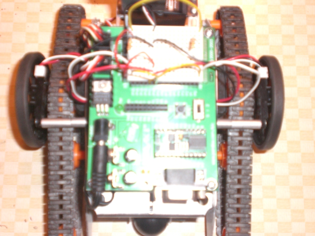
The key to making this work was to use Standoffs between the encoder and the boe-bot chassis (to get the sensor on the outer side of the tread).
Next, the orignal boe-bot wheel is also mounted with stand offs OVER/OUTSIDE OF the tread gear (which is mounted to the servo in the usual manner).
I have included some pics that I hope illustrate this better than words can.
Image 15 : Top Shot showing standoffs that position the encoders to the outside of the tread
Image 18 : Close up showing stand offs between tank tread main gear and the original boe bot wheel
Image 19 : Back Shot showing standoffs that position the encoders and the original boe-bot wheels
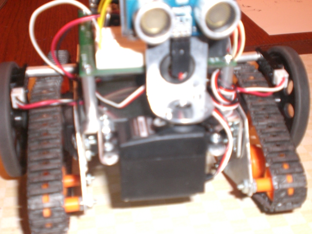
Image 20 : Front angle shot showing encoders "tucked up behind" the boe-bot wheels.


Comments
I'm an encoder fan, and I will be curious to see how well your treaded BoeBot works. Please advise and video if possible!
Erco - I'm still merging encoder and ping programs together. So, right now, this little boe-bot just kind of lurches around like a cockroach (grin). But it does go straight now (as well as forward).
-Phil
For a peek forward on the software front, what I have in mind is a sensors pipeline that will run in cogs that are separate from the drive-servo/encoder-counting cogs. The sensor cogs will generate messages to the drive-servo control cogs. The drive-servo cogs will just respond to this event stream (or will keep processing the last input message if no new message is present in their message queue). I hope to post more updates on that front over time.
As luck would have it, the spin-studio main board ( http://ucontroller.com/index_pro1.html ) will mount to the existing stand-offs on the boe-bot chassis. I like this board because of the "bus/slots" that it sports. Because, it is my opinion that designs like this make it easier for me to tinker a lot.
I will be using another of their boards to interface to the boe-bot servos and the front mounted ping: http://ucontroller.com/documentation/ioservodoc.html since it has the "standard servo three pin" arrangement already in place and it has the 1K limit resistors that are needed for the PING))) module too.
Next, I'll be using this board to hold the simple interface circuitry for the encoders: http://ucontroller.com/documentation/protocard.html ... but with a twist. Examining the copper traces on this board, anyone can see that it looks very much like the "innards" of any off-the-shelf bread board. That by itself is nice enough to be sure. But, if I can avoid melting solder on an experimental platform, I will (because, well, you know, I like to tinker a lot). So, I raided the parts bin and found a bunch of 16-pin SIP headers that I soldered on to this board, in order to make my own "bread board". See the attached images.
Well that's it for now. Hope this tip on making your own bread board is useful to someone else that lurks around here.
The whisker deck is is a small platform that I mounted on the outside of the ping-servo at the front that allows the mo'bot to sport whiskers as a means of sensing its surroundings. During my experiments with the mo-bot running various versions of roaming-with-ping code, I found that having whiskers would be have been a good thing.
I don't know about you all, but occassionally things go slightly awry with my programming and these little fellers tend to bump into things. So, I guess I'll call having whiskers a fail safe to be used when my adventures in programming don't work exactly right.
To add the whisker deck, I robbed a couple of angle mounts from an erector set. As an aside, I'd recommend at least one erector set to anyone that can't quite punch through on purchasing vex metal parts but still needs various light weight metal parts from time to time.
These angle mounts attach to the back side of the front-most idler pulley of the tread assembly. I bolted a standard radio shack circuit protoboard to the angle mounts. It turns out that the erector part and the circuit proto-board had holes drilled in exactly the right location for a couple of #4 machine screws that allows this protoboard to mount just to the outside of the ping servo.
To finish up the whisker deck, I attached a bread-board to the top of the proto-board with double sided adhesive. After the deck was completed, I built up a whisker system and an IR sensor system on to the bread board attached to the whisker deck.
Images here show the whisker deck, and how it is mounted to the mo'bot. Other images show how the spin studio is currently mounted on this mo'bot. I have to admit that I don't really care much for the "outrigger" style of the daughter boards (I think they are exposed in the crash-into-stuff-zone in this horizontal orientation). So, I'm waiting for some 90 degree gender changers that I found in the jameco catalog to see if I can get the spin "bus boards" to mount in a vertical orientation.
if the parts on order don't work according to plan, then I'll have to fabricate some myself with 90 degree pin headers soldered to the leads of a header socket.