

Waveform not nice
 BTX
Posts: 674
BTX
Posts: 674
Hi all.
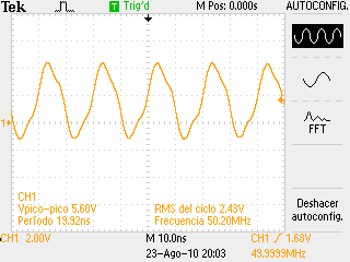
I'm testing a TDS2012B Tek O'scope (100Mhz bandwith), so I setup a Synth object to generate frequencies.
Playing with it, I get these measures (pictures attached).
I'm using my Parallax demo board.
Why the waves are like this ??, up to 40Mhz I'm getting almost a sinewave instead a square one.
Any ideas ?, is the new o'scope bad ? or what ? (the testing probe is a new one too, and for 200Mhz bandwith)
Thanks in advance for your opinion.

Comments
40 Mhz fundamental, +
120 Mhz 3rd harmonic
200 Mhz 5th harmonic
280 Mhz 7th harmonic... and so on
Your cro is attenuating the 3rd harmonic a bit, plus all the other harmonics increasingly severely. Hence the bumpy sine wave.
There will be other factors at play too - such as the circuit layout, and the slew rate of the prop outputs, etc. Perhaps someone with a nicer 1 Gig scope could post what it really looks like.
But the o'scope adquire at 1Gsps, 100Mhz is the input bandwith...so nothing to do ?
Forget to buy a new one
The problem is probably the inductance between the Prop pin and the scope. Or, the scope probe may not be properly tweaked. Sometimes they have a little screw you have to turn...
Nahh don't worry about it. It should still clock whatever chip you wish to clock with it. I've seen uglier clocks than the one you have that still work...
1Gsps sampling is great so you can draw lots of pretty line segments on the screen, but if the input amplifier bandwidth is 100 Mhz, that will cause a lot of distortion like you're seeing.
Yes it would pay to check the probe compensation to see if its blunting the waveforms slightly. But I suspect its more the 3db rolloff on the input section of the CRO. I'll see if I can see the same thing on my 150 Mhz scope with say a 50Mhz waveform
@Ray.
I've two scope probes to check, both same results, each of them are for 200Mhz....sorry I should be more close to Fourier....my fault...
@Tubular.
Nice idea, I would like to know, how do you see the waveform in your 150Mhz scope.
Imagine guys, this is my first DSO, I'm full of questions and surprissed for what I can see on his screen, (and my old 20Mhz analog scope is very jelous about that....).
This way, you should see more signal and less noise.
Graham
I must admit, it's pretty bad. No chance of seeing a square wave. It'll be either triangular or sinusoidal...
I'll be in the "stupid of the month" frame.
Yes, could write a square wave as:
sin(x) + 1/3 sin(3x) + 1/5 sin(5x) + 1/7 sin(7x) + .....
So, for 40Mhz signal with 2nd armonics at 120Mhz I'm lost.
For that kind of money, it's worth doing the work to get out of that device, and into another one.
Yes maybe I could return it, but I've not more money to waste in another one more expensive....
Anyway is much better than what I have before (analog 20Mhz), but I supossed more from this new one.... my fault.
Thank you!!
Still, there is a lot you can do with that scope. Every bit of progress counts.
This is handy for setting the probe capacitance. You should get a nice clean signal from this before measuring any outside signals.
@w8an: I did it before, the probe has a trimmer, but it is adjusted correctly. Thank you.
I don't have a 6.25 xtal to get 50 Mhz so I can't replicate what you're doing. In fact my xtal is 4.915200 hence the 39.2 Mhz
Don't worry. I'm sure your Tek will be a great investment
Don't despair. Even with a Prop, you will seldom encounter digital signals above 10 MHz. In any event, it's not unusual to have a twinge of buyer's remorse right after a large purchase. But you've acquired a quality piece of test equipment that will serve you well for years to come. Enjoy!
-Phil
Look at ray's page, he did some measurements of 80 and 100 MHz square signals with a 300 MHz scope (a dream machine!)... they also do not look perfectly square, but better than what you got (?).
Are you sure you have the right probes ? (some probes are rated up to 50 MHz...).
best regards,
Ale
For square waves do you really need a scope? They are so boring anyway
Cheers,
Graham
Correct, your wave form is similar as I can se in mine.....maybe all is explained in this thread for those who want to buy an scope next time. About what to expect.
@Phil.
Be quiet, I'm really happy anyway, each day I try differents measures, and I can see that it will help me a lot in work !!... a lot. Thank you.
@Ale.
I will see the Ray's site then.
And my probes comes with the scope, they are for 200Mhz in X10 attenuation. they are P2220 1x-10x passive probes. Thank you.
@Graham.
Of course !! my scope view is more funny !!
To be usefull for other people, I want to comment something in this thread. Correct me if I'm wrong.
If I really don't understand bad about this theme, when you want to buy an scope, don't forget that it comes with "analog inputs", and if is not usually to acquire analogs inputs of very high frequencies for you, and If you'll need to check very high frequencies square waves instead, think in a scope with digitall inputs too, ie: the Tek: MSO series. Maybe it is cheaper than a analog scope with a very high bandwith, and more suitable for square waves.
Another point in this thread is for Tubular.
I used the Synth Object to check this, you can get almost any frequency using this, no needs to change the xtal. Download it form the Propeller Object Exchange and try.
Thank you so much everybody to help me on this. !!
Interesting tip.
http://www.univie.ac.at/future.media/moe/galerie/fourier/fourier.html
Click the big red rectangle, choose "examples" then the square wave box. Then play with the coefficients. It's not well labelled, but the left half of the screen is for even harmonics, and the right half is the odd harmonics.
You get a real education in all this when you test for output ripple & noise, stuff like that.
Nice illustration! The tricky part is getting that little loop of wire around the ground sleeve to stay put. Copper wire just isn't springy enough to grip tightly. I sometimes resort to shrink tubing to keep it it firm contact with the probe. I suppose a loop of music wire would be the best bet.
-Phil