Shop OBEX P1 Docs P2 Docs Learn Events
Encoder wheel with 36 position > 72 — Parallax Forums

Encoder wheel with 36 position > 72

pvdbpvdb Posts: 8
edited 2010-08-22 12:02 in Robotics
Hello.
I have a question about the Motor Mount and Wheel Kit with Position Controller, this controller have an encoder wheel with 36 position per revolution, approx. 0.5 inch resolution.
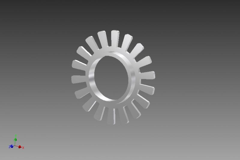
Now is my question can I make a encoder wheel with 72 position per revolution to make ¼ inch resolution? and wil this work!?.
800 x 534 - 19K

Comments

  • kwinnkwinn Posts: 8,697
    edited 2010-08-21 13:19
    You may not need to change encoder wheels. The tabs and spaces on the encoder wheel look like they are symmetrical so you can use the transitions from light to dark to light to get twice the resolution.
  • ercoerco Posts: 20,257
    edited 2010-08-21 16:14
    OK, you're showing a drawing you're proposing (18 slots) which has twice the resolution of the stock units, which only have 9 slots, right?

    AFAIK, this is a quad encoder (2 optical sensors). Thus the stock 9-slot unit gives 9x4=36 PPR. So yes, your proposed 18-slot disk will yield 72 PPR, provided the slots & tabs don't get smaller than the optical sensor can read. For reliability, you want a 50-50 duty cycle output from the optical sensors. That is, the angular rotation of the on & off segments are equal.
  • Phil Pilgrim (PhiPi)Phil Pilgrim (PhiPi) Posts: 23,514
    edited 2010-08-21 16:42
    Doubling the number of slots won't work, sorry to say. The reason is that the two sensors are spaced n + 1/2 slots apart to provide quadrature outputs. With twice as many slots, they'd be spaced 2n+1 slots apart, and would not provide outputs in quadrature with each other. But if you triple the number of slots, they will be spaced 3n + 3/2 slots apart and back in quadrature with each other. The optical resolution of the sensors also has to be taken into consideration. As a result, although any odd multiplier will work, 3X is probably the absolute maximum limit, and even that may be too much.

    Here's an illustration:

    attachment.php?attachmentid=72653&stc=1&d=1282434861

    -Phil
    600 x 261 - 12K
  • Capt. QuirkCapt. Quirk Posts: 872
    edited 2010-08-22 01:31
    Why don't you just measure the time between edges. After you have measured the time, make it := old time. Then use "old time/2" (Example: Do something when New Time == Old Time/2) to get your greater resolution.
  • LeonLeon Posts: 7,620
    edited 2010-08-22 05:32
    Speed and direction are generally required.
  • ercoerco Posts: 20,257
    edited 2010-08-22 08:03
    So true, Phil! I have always scratch-build my encoders and I failed to take this unit's predetermined sensor spacing into account.

    pvdb: You're a hacksaw and some superglue away from a 72 PPR quad encoder!

    Also true that quad encoders give speed & direction. I had fabulous results (accuracy and repeatability) on Retrobot with just 36 PPR using not a quad encoder, but one optical sensor, which according to Wikipedia is called a tach sensor, not a real encoder. A tach sensor does not give direction, but is faster & easier to read than a quad encoder. In most robot applications, it's pretty dang easy to guess the direction of rotation, isn't it?
  • Phil Pilgrim (PhiPi)Phil Pilgrim (PhiPi) Posts: 23,514
    edited 2010-08-22 12:02
    Yup. Direction feedback can be optional if you know which way the motor is turning (and you usually do, since your program is driving it). In the S2, for example, only one sensor is used with each encoder. But the gear reduction ratio is so high that the encoder shaft turning without being motor-driven is well nigh impossible.

    BTW, What Capt. Quirk is suggesting could be thought of as a phase locked loop with a frequency divider. This would very difficult to implement, due to the possibility of rapid accelerations and decelerations.

    -Phil
Sign In or Register to comment.