Shop OBEX P1 Docs P2 Docs Learn Events
Controlling a motor with two potentiometers — Parallax Forums

Controlling a motor with two potentiometers

velociostrichvelociostrich Posts: 40
edited 2010-08-20 13:46 in General Discussion
I have a project that I'm working on (well, still planning anyway) that requires a short linear motion that could be achieved with a solenoid, but as the only ones I could find that were the right size were rather expensive, and would require some relatively complex driving circuitry, I've tried to think of a way to do the same with readily available parts. The solution I've thought of involves the use of a motor that in some way either drives a cam that pushes a rod, or turns a threaded shaft that then moves a threaded tube around it, or perhaps by some other means produces a short (about 1/8"), linear stroke. Anyways, I thought about having a linear potentiometer control the rotation of a motor to a specific angle by hooking up a potentiometer to the shaft of the motor, and wiring both in parallel. Both would act as voltage dividers, and the potential difference between the wipers of the two would, I hypothesized, make the motor turn until its own rotation turned the potentiometer attached to the shaft enough that its resistance equalled the linear pot and the potential difference between the two was zero. So naturally, I tried making such a circuit with what parts I had, testing the potential difference between wipers with my digital multimeter, and found my hypothesis was, seemingly, correct. Excited, I attached a small DC motor to the circuit... and it didn't turn. I checked the circuit again and found that there was no current between the wipers. Am I doing something wrong, or is my idea flawed? Or is there some other way of achieving this? I've made a schematic and attached it illustrating the circuit I tried.
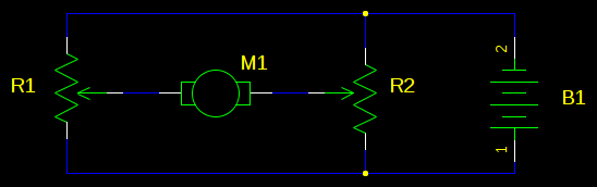
548 x 172 - 4K

Comments

  • ercoerco Posts: 20,260
    edited 2010-08-19 14:12
    Motor control using pots is a losing battle. You lose torque and efficiency. If you want to try at all, you need a low value rheostat, the Shack has a 25-ohm one for $4: http://www.radioshack.com/product/index.jsp?productId=2062299


    Better idea: use a pot to drive a servo 180 degrees, and put a gear on the servo output, which drives a rack for linear motion. Very efficient. You can use a Stamp or build a "servo tester" circuit to control the servo using a 5K or 10K pot.
  • LeonLeon Posts: 7,620
    edited 2010-08-19 16:04
    Use a stepper motor. They are available with linear motion attachments.
  • velociostrichvelociostrich Posts: 40
    edited 2010-08-19 19:00
    I'd use a servo, but it has to actuate very quickly, and must also be small -- I do have a few small ones, but I don't know if they even have enough torque or if I could get one with a rack and pinion small enough. Still, that's an interesting idea. A stepper motor, however, may work, as the shaft is in the center (something necessary that I failed to mention) and they have a decent amount of torque. Anyways, thanks for the advice!
  • T ChapT Chap Posts: 4,223
    edited 2010-08-19 22:46
    You can accomplish the idea of having a pot move something relative to where the pot is. You will have to invest some time and energy into this, but the result will be rewarding. You will need the Propeller, a linear pot, a stepper driver and a stepper motor. There are other ways to do it but I think it would be too complex for you to try to jump right into. Using a servo with a DC motor or Brushless DC motor would be nice, but then you are getting into more complex software and hardware. A bipolar stepper is pretty simple, especially if you buy an off the shelf stepper driver module like a Gecko 212 for example, that takes step and direction inputs. I have some code that would manage the motion of the steppers, all you do is feed the code a position, it calculates the actual position of the stepper compared to the position it is sent, and ramps the stepper up and down towards the position. You will need ramping if you expect to run at any speeds with a stepper. The first thing is to get the linear pot, and read the wiper into the input of the Propeller by its own simple ADC method. Then, you use the resulting ADC value as the position that is constantly getting fed to the loop that manages the stepper. As you turn the pot, the ADC value changes, and the stepper chases the position.

    If you want to start out trying to build your own hbridge, you will learn a lot but there is a learning curve and frustration factor going that route. It all depends on what your goal is, if you just need to get the project up as fast as possible, buy an off the shelf stepper bipolar driver and hook a Prop up to it and your are in business.
  • anhingusanhingus Posts: 10
    edited 2010-08-20 01:29
    use pulley on motor to turn another pulley. itty-bitty neobdymium magnet on rubberband, chain, etc, connecting pulleys. hall-effect sensor at magnet travel end to kill motor power.
    gearhead motor for desired speed of linear action, stepper only if extreme precision needed.

    cheaper, i would think, than using pots that can handle power.
  • velociostrichvelociostrich Posts: 40
    edited 2010-08-20 13:46
    For the project I'm working on, whatever board I make has to be very small (5/8" by 1-15/16") and whatever I concoct for a linear actuator of sorts would have to be similarly small (1" in diameter by 3/4" in length) -- after some more head scratching, I'm thinking about using a small DC motor (which I have on hand) and probably using a microcontroller to drive it. I'd use the Prop, but I think it's totally overkill, so instead I may go with an OEM BASIC Stamp 1 even though it's a tad more expensive.
Sign In or Register to comment.