

Help explain this circuit (variable speed drill)
 mpark
Posts: 1,336
mpark
Posts: 1,336
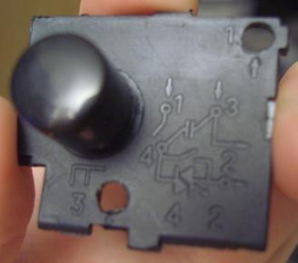
I'm trying to understand the speed control circuit of a variable speed drill (AC powered) with the ultimate aim of controlling it via Propeller. There's this sort of schematic printed on it:

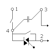
I've redrawn it here:

Points 1 and 3 are the power cord. There are two switches; one closes when you start to pull the trigger, the second closes once the trigger is pulled all the way.
I am guessing that the two right-pointing arrows go to a variable resistance as set by the trigger.
Questions:
1. What is the double-diode-looking thingie, and why does it have a third leg floating?
2. Does the schematic (such as it is) make sense? How does it work?
Thanks for any insights.
Post Edited (mpark) : 8/4/2010 11:04:44 AM GMT
I've redrawn it here:
Points 1 and 3 are the power cord. There are two switches; one closes when you start to pull the trigger, the second closes once the trigger is pulled all the way.
I am guessing that the two right-pointing arrows go to a variable resistance as set by the trigger.
Questions:
1. What is the double-diode-looking thingie, and why does it have a third leg floating?
2. Does the schematic (such as it is) make sense? How does it work?
Thanks for any insights.
Post Edited (mpark) : 8/4/2010 11:04:44 AM GMT
328 x 290 - 43K
187 x 189 - 2K
Comments
en.wikipedia.org/wiki/TRIAC
I remember when they first became available, around 1970. I bought a couple from the RCA distributor and built a similar speed controller for my electric drill.
The schematic is wrong, the gate should be connected to the pot. I can't remember the exact arrangement but you should be able to find it. I'd use opto-isolators if it is to be controlled by a Propeller.
▔▔▔▔▔▔▔▔▔▔▔▔▔▔▔▔▔▔▔▔▔▔▔▔
Leon Heller
Amateur radio callsign: G1HSM
Post Edited (Leon) : 8/4/2010 11:37:52 AM GMT
-Phil
One problem though: when I turn the system on or off, the drill runs for a short time. This happens about half the time. I'd prefer it not run at all unless told to. I'm using the circuit below (except it's 120V across the load). Any suggestions?
Post Edit -- A "snubber" is analogous, you might figure, to a free-wheeling diode placed across a relay coil, etc.
http://en.wikipedia.org/wiki/Snubber