

New XBee SIP Adapter from Parallax($24.99) - you'll like this design!
 Ken Gracey
Posts: 7,420
Ken Gracey
Posts: 7,420
www.parallax.com/Store/Accessories/CommunicationRF/tabid/161/ProductID/691/List/0/Default.aspx?SortField=ProductName,ProductName
Hey all,
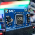
We've just released a really high-quality, well-thought out design for the XBee modules. If you've ever wanted to just "plug it into a breadboard" this adapter is your solution. The key I/Os (Vss, Vdd, Sin, Sout, RTS) are ported to the right-angle header. All other XBee I/Os are available with solder pads. You can install a m/m or m/f header to access them.
And most importantly, this is the adapter that will be used in our future educational tutorials. It's 5V compliant and fully specified by our Education department.
It's priced at $24.99, which may seem a bit high to some people. However, it comes fully assembled and tested from our Rocklin, CA facility.
▔▔▔▔▔▔▔▔▔▔▔▔▔▔▔▔▔▔▔▔▔▔▔▔
Ken Gracey
Parallax Inc.
Follow me at http://twitter.com/ParallaxKen for some insider news.
Hey all,
We've just released a really high-quality, well-thought out design for the XBee modules. If you've ever wanted to just "plug it into a breadboard" this adapter is your solution. The key I/Os (Vss, Vdd, Sin, Sout, RTS) are ported to the right-angle header. All other XBee I/Os are available with solder pads. You can install a m/m or m/f header to access them.
And most importantly, this is the adapter that will be used in our future educational tutorials. It's 5V compliant and fully specified by our Education department.
It's priced at $24.99, which may seem a bit high to some people. However, it comes fully assembled and tested from our Rocklin, CA facility.
▔▔▔▔▔▔▔▔▔▔▔▔▔▔▔▔▔▔▔▔▔▔▔▔
Ken Gracey
Parallax Inc.
Follow me at http://twitter.com/ParallaxKen for some insider news.
Comments
It isn't clear from the picture but it looks like there are only 5 signals brought out to the 10-pin header and that each signal is on a pair of pins. I can see that would certainly help keep the module in place when plugging the module into a breadboard or socket with the extra row of pins.
Very nice! With all these cool adapters I am going to have to try out these XBee modules.
Robert
You still want to use the other 433 mHz RF Linx modules for the current project you mentioned in the PM to me, right? I can get those out to you today. Let me know.
▔▔▔▔▔▔▔▔▔▔▔▔▔▔▔▔▔▔▔▔▔▔▔▔
Ken Gracey
Parallax Inc.
Follow me at http://twitter.com/ParallaxKen for some insider news.
RobotWorkshop, just to clarify, there are 5 signals brought out to the male 2x5 header:
GND
+5V
DOUT
DIN
/RTS
(Yes the 2x5 pin arrangement was chosen for stability, after we witnessed kids trying to use our 433 MHz transceiver modules like joysticks on a robot tilt-controller application at the State Fair. )
5 more pins are accessible through a female header that is already installed:
ASSOC
RSSI
/RST
SLP
/CTS
All the above pins are buffered.
The last 10 pins are NOT buffered, but they are accessible from the plated through-holes, so you have the option to add another header:
IO0
IO1
IO2
IO3
IO4
IO5
IO6
IO7
VREF
PWM1
One extra through-hole was added: 3.3 V output for ADC reference when needed.
Hope this helps!
-Steph
The XBee adapter board was being hard to fit, so I ran some jumper wires between the the demo board & adapter board.
Their on my wish list, now to have payday get here (& some extra cash hopefully).
Thanks
Jay
How hard would it be to remove the right angle headers and put in straight headers from the bottom? Same with the 5 pin female header, have 5 pin male header below.
With the right angle the board will stick up vertically too high, I would like the board horizontal (parrallel) to the main board with the XBee on top...
Maybe as an option don't solder the headers, or just don't include the headers?
Either ways, thanks! I'm sure I will be ordering 2 or 3 in the next month or two.
Thanks
Jay
Great job!
I was looking for some info on it and nothing back on google or Digikey. 74lc244 yes but not
the number on the drawing.
Thank's
Tom
John Abshier
Not that I'm complaining, but it's a little odd for a device with a 2 rows of pins referred to as the "SIP Adapter", isn't it?
@Jay: All of the headers are hand-soldered by our wonderful manufacturing folks, so I'm not sure how easy they would be to remove. This product was mainly designed for educational use, since as you mentioned the other boards take up a lot of breadboard 'real estate' and would take up a lot of space on a Boe-Bot's breadboard. It also puts some strain on most teachers to solder every board needed for classroom use (and many high schools don't have soldering options available to students), it's easiest to have everything pre-assembled so teachers can use everything straight out of the bag.
@tdlivings: The part number is correct in the schematic: 74LVC244A. I can see where the font used makes the 'V' look like a 'Y' though!
@John: The supply voltage should be 5V, we've fixed that now, thanks for pointing it out. With a 5V supply, the board is still compatible with the Propeller, since the XBee is a 3.3V device as well, and all output from the XBee to Propeller will be at 3.3V.
@sylvie: Since the dual rows connect to the same pins on the board and are only there for stability, we figured it fell into a 'gray area' of naming conventions and still could qualify as a SIP Adapter. Just think of it as getting more bang for your buck. ;]
Hope this helps, let us know if you have any other questions!
-- Jessica
▔▔▔▔▔▔▔▔▔▔▔▔▔▔▔▔▔▔▔▔▔▔▔▔
Jessica Uelmen
Education Department
Parallax Inc.
E-mail me your shipping information and we'll figure out how to get these to you.
▔▔▔▔▔▔▔▔▔▔▔▔▔▔▔▔▔▔▔▔▔▔▔▔
Ken Gracey
Parallax Inc.
Follow me at http://twitter.com/ParallaxKen for some insider news.