

Program to fully test the propeller for new QFN-DIP40 module?
 WBA Consulting
Posts: 2,940
WBA Consulting
Posts: 2,940
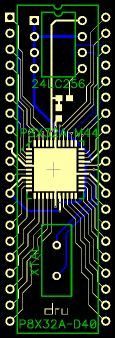
So, I just got my PCBs for my QFN to DIP40 (plus EEPROM/xtal/propplug hdr) module (that I am calling the M44D40+) and even though it may be a while before I get one made up, I am thinking of how to test them. Anyone have a SPIN program that exercises all pins for input and outputs like the Basic Stamp tester does for the stamp? I know I could do something that simple, but shouldn't I test video generation, multiple cogs, etc, or use the "if it works, it works" concept?
▔▔▔▔▔▔▔▔▔▔▔▔▔▔▔▔▔▔▔▔▔▔▔▔
Andrew Williams
WBA Consulting
PowerTwig Dual Output Power Supply Module
My Prop projects: Reverse Geo-Cache Box, Custom Metronome, Micro Plunge Logger
Post Edited (WBA Consulting) : 7/13/2010 6:04:24 PM GMT
▔▔▔▔▔▔▔▔▔▔▔▔▔▔▔▔▔▔▔▔▔▔▔▔
Andrew Williams
WBA Consulting
PowerTwig Dual Output Power Supply Module
My Prop projects: Reverse Geo-Cache Box, Custom Metronome, Micro Plunge Logger
Post Edited (WBA Consulting) : 7/13/2010 6:04:24 PM GMT

448 x 168 - 19K
115 x 338 - 17K
Comments
While I haven't studied the problem thoroughly, it makes sense to make the test unit "UUT" as busy as possible while providing some easy ways to measure the effects potential problems. A quick static test could be done with pin loop-backs, but may not catch all soldering issues.
I propose this:
1. Have a program that tests/runs VGA on pins P0-7, P8-15, P16-23, and TV on P24-27 simultaneously. 2. Download to EEPROM and reboot to see test pattern on all 4 displays (look for artifacts and bad colors). 3. BOEn can allow control of RESn power up state. Set low for normal operation. Set high for RESn as input.
Video checks the crystal precision (look for video artifacts), connectivity of pins/pads (look for proper colors), puts some burden on the Propeller (runs several cogs). Download/boot from EEPROM checks RESET and P28-31 (an erase program can be used after testing). Brownout can be checked different ways, but I can't remember the exact details just now.I'm sure there are other ideas out there too. I'm happy to help however I can.
Cheers,
--Steve
▔▔▔▔▔▔▔▔▔▔▔▔▔▔▔▔▔▔▔▔▔▔▔▔
Propeller Pages: Propeller JVM
▔▔▔▔▔▔▔▔▔▔▔▔▔▔▔▔▔▔▔▔▔▔▔▔
Links to other interesting threads:
· Home of the MultiBladeProps: TriBlade,·RamBlade,·SixBlade, website
· Single Board Computer:·3 Propeller ICs·and a·TriBladeProp board (ZiCog Z80 Emulator)
· Prop Tools under Development or Completed (Index)
· Emulators: CPUs Z80 etc; Micros Altair etc;· Terminals·VT100 etc; (Index) ZiCog (Z80) , MoCog (6809)·
· Prop OS: SphinxOS·, PropDos , PropCmd··· Search the Propeller forums·(uses advanced Google search)
My cruising website is: ·www.bluemagic.biz·· MultiBlade Props: www.cluso.bluemagic.biz
cluso, thanks, I will take a peek at your program. From what I can gather, making a custom program will be best.
for the first one, I am just going to place the QFN, check for shorts, then throw it onto my hydra. That will tell me quite a bit.
▔▔▔▔▔▔▔▔▔▔▔▔▔▔▔▔▔▔▔▔▔▔▔▔
Andrew Williams
WBA Consulting
PowerTwig Dual Output Power Supply Module
My Prop projects: Reverse Geo-Cache Box, Custom Metronome, Micro Plunge Logger
I'm glad you're not worried about soldering; I would be seriously worried if I had to solder a QFN.
When will your parts be available for sale?
Can you manufacture something with a part like this?
Cheers,
--Steve
▔▔▔▔▔▔▔▔▔▔▔▔▔▔▔▔▔▔▔▔▔▔▔▔
Propeller Pages: Propeller JVM
▔▔▔▔▔▔▔▔▔▔▔▔▔▔▔▔▔▔▔▔▔▔▔▔
Andrew Williams
WBA Consulting
PowerTwig Dual Output Power Supply Module
My Prop projects: Reverse Geo-Cache Box, Custom Metronome, Micro Plunge Logger
▔▔▔▔▔▔▔▔▔▔▔▔▔▔▔▔▔▔▔▔▔▔▔▔
Andrew Williams
WBA Consulting
PowerTwig Dual Output Power Supply Module
My Prop projects: Reverse Geo-Cache Box, Custom Metronome, Micro Plunge Logger
▔▔▔▔▔▔▔▔▔▔▔▔▔▔▔▔▔▔▔▔▔▔▔▔
Andrew Williams
WBA Consulting
PowerTwig Dual Output Power Supply Module
My Prop projects: Reverse Geo-Cache Box, Custom Metronome, Micro Plunge Logger
Those Spin-studio VGA adapters look very attractive for a multi VGA test. Even the TV adapter could be used with a hack. Maybe you can chop off the plastic from the IDCs and fit them on a Propeller Platform (or just buy a Spin-studio main board). Would happen to have a 40 pin ZIF connector or two?
Cheers,
--Steve
▔▔▔▔▔▔▔▔▔▔▔▔▔▔▔▔▔▔▔▔▔▔▔▔
Propeller Pages: Propeller JVM
As for the ZIF sockets, I happened to get some off eBay a while ago and still have a few.
▔▔▔▔▔▔▔▔▔▔▔▔▔▔▔▔▔▔▔▔▔▔▔▔
Andrew Williams
WBA Consulting
PowerTwig Dual Output Power Supply Module
My Prop projects: Reverse Geo-Cache Box, Custom Metronome, Micro Plunge Logger
▔▔▔▔▔▔▔▔▔▔▔▔▔▔▔▔▔▔▔▔▔▔▔▔
Andrew Williams
WBA Consulting
PowerTwig Dual Output Power Supply Module
My Prop projects: Reverse Geo-Cache Box, Custom Metronome, Micro Plunge Logger
Post Edited (WBA Consulting) : 7/11/2010 4:34:35 AM GMT
While there is a remote (very remote, I should think) possibility that the Prop itself is bad, the tests should initially focus on the external wiring. My first test of all uncommitted (floating) pins is the charge and discharge exercise using the gate capacitance as dynamic memory to test for shorts or leakage between pins and to the power supplies. It goes like this. Set all uncommitted pins for output low. Set same pins for input. Wait 0.01 second (configurable). Check same pins. All should still be low. Do the same for output high, delay, test for high. Do the same for alternating pattern %101010... Then the same for opposite alternating pattern %010101... It is also possible to include inputs that have pullups or pulldowns, but of course the expected state should always be high or low and a discrepancy indicates an open connection to the Prop.
The circuit like the RC Stamp tester is even better, because it better tests for open connections from the pads to the circuit, and higher drive current capability. It tests all uncommitted pins for capability of output high, low and input, and detects shorts or leakage between pins and to the power supply rails.
For pins that are dedicated to function, serial port, eeprom, reset, and other peripherals, test for function and if it works, that is a pretty good indication that the prop connections are good. If it doesn't, well, troubleshooting starts!
Put the board through a temperature cycle to help reveal cold solder joints. Test the chip on a current limited supply while monitoring voltage and current, to detect power supply connection issues. Take the chip to RCslow to test power leakage.
Good shots, thanks. Maybe a side or end profile too to show how the stackable headers compare to the height of the EEPROM and crystal.
It seems that best way would be to generate a 1280x1024 VGA signal, using only 2 pins at a time for video data (plus 2 for sync of course), starting with P31 and P30, and going down by a pair until you reach P3 and P4. Then display a 64x64 checker board pattern. Once this is done repeat with 3 cogs, and 6 video signal (8 including sync) pins with each cog driving 2 pins, start with group 24-31 and move down from there. This should make any errors very self apparent, as I you will see distortions in the image if the board is creating to much unwanted noise of any type. Also for both sets of tests you will want to display a pattern of 1 pix wide vertical stripes separated by 1 pixel. And f course use your scope.
I hope that I am not to late to dinner here. I came up with this simple test because I was noticing some strange behavior sometimes and it looked good on the scope, but this showed me that there was noise that my scope could not show me (later verified with a better scope).
One of the pictures shows the module talking to a Xbee wireless radio..
Yay! First Production Run photo! I will also have full pictures of the build process written up soon. Got a handful ready for final testing for UPEW. Apart from a few that are reserved, I should have ~10 available for sell at UPEW.