

1st Diptrace Project attempt! Thank you Nick
 Oldbitcollector (Jeff)
Posts: 8,091
Oldbitcollector (Jeff)
Posts: 8,091
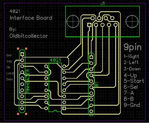
So I'm working on some 1/3 scale arcade machines for UPENE.
I didn't want to dissect NES controllers again, hence the question a couple days ago.
Thanks to a couple good answers, I've got some 4021's (.25c from Hong Kong on their way)
I thought this would be a good opportunity to whip out some Diptrace time with this simple circuit.
(Yes, I'm sure I could zap this up with a Radio shack perf board in the time I spent already, but..)
For some reason I couldn't get nice .1 holes where I wanted them, so I wound up using a second resistor array
in my schematic. I set the autoroute to single layer so I could do some "pcb-at-home" experiments.
Here's the result. Anyone see any glaring errors before I go to ironing this to some copper clad?
Thanks!
OBC
▔▔▔▔▔▔▔▔▔▔▔▔▔▔▔▔▔▔▔▔▔▔▔▔
Propeller Feature Projects: PropellerPowered.com
Visit the: PROPELLERPOWERED SIG forum kindly hosted by Savage Circuits.

Comments
There is no decoupling capacitor.
You have one right angle track, and an acute angle.
You might have problems with some of the pads, I'd make them bigger. I use oval pads on DILs with home-made PCBs.
▔▔▔▔▔▔▔▔▔▔▔▔▔▔▔▔▔▔▔▔▔▔▔▔
Leon Heller
Amateur radio callsign: G1HSM
Post Edited (Leon) : 7/4/2010 4:32:16 AM GMT
I've already made changes including rewiring the 9pin connector for atari compatibility.
OBC
▔▔▔▔▔▔▔▔▔▔▔▔▔▔▔▔▔▔▔▔▔▔▔▔
Propeller Feature Projects: PropellerPowered.com
Visit the: PROPELLERPOWERED SIG forum kindly hosted by Savage Circuits.
I believe this fits the rules that I am aware of for pcb trace routing. I used ExpressPCB, since it was free.
This is the first time I have done this kind of thing. So if have a moment to let me know what I did wrong, that would be great.
Also, since R1 is a resister block I assumed I could route through it differently than you did and it would be the same end result.
▔▔▔▔▔▔▔▔▔▔▔▔▔▔▔▔▔▔▔▔▔▔▔▔
Check out the Propeller Wiki·and contribute if you can.
▔▔▔▔▔▔▔▔▔▔▔▔▔▔▔▔▔▔▔▔▔▔▔▔
Leon Heller
Amateur radio callsign: G1HSM
▔▔▔▔▔▔▔▔▔▔▔▔▔▔▔▔▔▔▔▔▔▔▔▔
www.fd.com.my
www.mercedes.com.my
I've noticed that you use wire links on your boards, perhaps you could give us an example of how you would do this.
Regards,
Coley
▔▔▔▔▔▔▔▔▔▔▔▔▔▔▔▔▔▔▔▔▔▔▔▔
PropGFX - The home of the Hybrid Development System and PropGFX Lite
I use thin tinned copper wire for the links, it's flexible so I can "stitch" several connections together for complex boards with the links close to each other. I then cut them on the underside.
▔▔▔▔▔▔▔▔▔▔▔▔▔▔▔▔▔▔▔▔▔▔▔▔
Leon Heller
Amateur radio callsign: G1HSM
(red wires signify links)
▔▔▔▔▔▔▔▔▔▔▔▔▔▔▔▔▔▔▔▔▔▔▔▔
PropGFX - The home of the Hybrid Development System and PropGFX Lite
▔▔▔▔▔▔▔▔▔▔▔▔▔▔▔▔▔▔▔▔▔▔▔▔
Leon Heller
Amateur radio callsign: G1HSM
Perhaps you can show us what you mean in a layout??
▔▔▔▔▔▔▔▔▔▔▔▔▔▔▔▔▔▔▔▔▔▔▔▔
PropGFX - The home of the Hybrid Development System and PropGFX Lite
▔▔▔▔▔▔▔▔▔▔▔▔▔▔▔▔▔▔▔▔▔▔▔▔
Leon Heller
Amateur radio callsign: G1HSM
Post Edited (Leon) : 7/4/2010 1:28:31 PM GMT
(Time to watch Nick's videos again)
Edit: Flood-fill might not be a good idea being that this design is going to be used for a single sided home pcb fab. Thoughts?
I know; I'm like a proud papa of a really ugly baby, but I'm hoping the end result works. [noparse]:)[/noparse]
OBC
▔▔▔▔▔▔▔▔▔▔▔▔▔▔▔▔▔▔▔▔▔▔▔▔
Propeller Feature Projects: PropellerPowered.com
Visit the: PROPELLERPOWERED SIG forum kindly hosted by Savage Circuits.
Post Edited (Oldbitcollector) : 7/4/2010 6:16:51 PM GMT
▔▔▔▔▔▔▔▔▔▔▔▔▔▔▔▔▔▔▔▔▔▔▔▔
Propeller Feature Projects: PropellerPowered.com
Visit the: PROPELLERPOWERED SIG forum kindly hosted by Savage Circuits.
Post Edited (Oldbitcollector) : 7/4/2010 6:39:22 PM GMT
I suggest you post your schematic, along with the PCB layout. Sometimes simple changes in the schematic can greatly simplify the layout of a board. I am guessing that R1 is a resistor pack with 1 side of each resistor connected together (to GND)? If this is true it does not matter what resistor is used for which signal, and swapping some of them would simplify the layout of your board.
Regards,
zappman
▔▔▔▔▔▔▔▔▔▔▔▔▔▔▔▔▔▔▔▔▔▔▔▔
Visit Zappman's Blog at Savage Circuits
▔▔▔▔▔▔▔▔▔▔▔▔▔▔▔▔▔▔▔▔▔▔▔▔
Leon Heller
Amateur radio callsign: G1HSM
R
▔▔▔▔▔▔▔▔▔▔▔▔▔▔▔▔▔▔▔▔▔▔▔▔
UC Berkeley '12 EECS
CalSol: UC Berkeley Solar Car
http://calsol.berkeley.edu
KJ6AWU
I also just discovered today that Parallax has several DipTrace project files on the Open-Source Hardware Designs page, including the Propstick USB.
▔▔▔▔▔▔▔▔▔▔▔▔▔▔▔▔▔▔▔▔▔▔▔▔
Andrew Williams
WBA Consulting
PowerTwig Dual Output Power Supply Module
My Prop projects: Reverse Geo-Cache Box, Custom Metronome, Micro Plunge Logger
▔▔▔▔▔▔▔▔▔▔▔▔▔▔▔▔▔▔▔▔▔▔▔▔
Andrew Williams
WBA Consulting
PowerTwig Dual Output Power Supply Module
My Prop projects: Reverse Geo-Cache Box, Custom Metronome, Micro Plunge Logger
Actually the project for the mini arcades didn't come up until Matthew and I had a chance to talk on the return flight.
We were discussing how difficult it might be to bring the Propeller Arcade to UPENE without breaking it, when
Matthew suggested that we might build some mini arcade machines.
Instead of hacking apart a NES controller and building an interface from it I thought it might be time to reach forward
again and tackle a couple new skills which have been on my list for a while now.
OBC
▔▔▔▔▔▔▔▔▔▔▔▔▔▔▔▔▔▔▔▔▔▔▔▔
Propeller Feature Projects: PropellerPowered.com
Visit the: PROPELLERPOWERED SIG forum kindly hosted by Savage Circuits.
cgi.ebay.com/1980s-COLECO-FROGGER-MINI-ARCADE-TABLE-TOP-SEGA-GAME-/380219383829?cmd=ViewItem&pt=LH_DefaultDomain_0&hash=item5886d76015
▔▔▔▔▔▔▔▔▔▔▔▔▔▔▔▔▔▔▔▔▔▔▔▔
Andrew Williams
WBA Consulting
PowerTwig Dual Output Power Supply Module
My Prop projects: Reverse Geo-Cache Box, Custom Metronome, Micro Plunge Logger
This is based on the side panel being 1x12x
(Actually Bryan Cartwright (UPE fame) is working out the exact dimensions as he's a wiz with illustrator)
OBC
▔▔▔▔▔▔▔▔▔▔▔▔▔▔▔▔▔▔▔▔▔▔▔▔
Propeller Feature Projects: PropellerPowered.com
Visit the: PROPELLERPOWERED SIG forum kindly hosted by Savage Circuits.