

NEW: Propeller Platform USB
 Nick McClick
Posts: 1,003
Nick McClick
Posts: 1,003
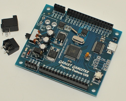
The Propeller Platform USB includes a Propeller with removable 5MHz crystal, USB programming circuit, dual 1.5A very low dropout regulators, and a DS1307 Realtime clock.
Project Page
Specs
These differ from Rev. C (which should be available in about a month) in a few ways;
They're available for $45 right here. Let me know if you have any questions!
Nick
▔▔▔▔▔▔▔▔▔▔▔▔▔▔▔▔▔▔▔▔▔▔▔▔
Propeller Forums RSS Feed!
Gadget Gangster - Share your Electronic Projects
Project Page
Specs
- 2.8" x 2.5"
- Compatible with all other Platform Modules (DMX IO, LCD UI, ProtoPlus, El Jugador, OctoDriver, PropNet, Prototyper, Tester, Battery, VGA A/V, Servo Module, PropNet).
- Pre-assembled and tested (schematic), except for the power connector - it comes with a screw terminal and barrel jack, and you can solder on the one you prefer to use.
- Includes 64k EEPROM, 5Mhz socketed crystal, USB, and DS1307 Real-time Clock with Super Capacitor power bakcup
- Super low dropout regulators - they'll run within 100mV of the output voltage, so 5.1v input minimum.
These differ from Rev. C (which should be available in about a month) in a few ways;
- Rev. C will have a microSD slot instead of a Real-time clock
- Rev. C will have 3 power indicator LED's
They're available for $45 right here. Let me know if you have any questions!
Nick
▔▔▔▔▔▔▔▔▔▔▔▔▔▔▔▔▔▔▔▔▔▔▔▔
Propeller Forums RSS Feed!
Gadget Gangster - Share your Electronic Projects
Comments
What about a Rev D. board that has the RTC and the SD in the spot you have the headers for the propplug/propclip since you have the usb interface.. ??
Also I like the face the rev C board has more led indicators.. lots lights are always nice.. or even a single rgb would be cool..
And what are the chances of getting a socket/header to the i2c bus so one could easily add in Rayman's accelerometer or even a replacement rtc??
KPR..
Oh.. any pics of rev C??
▔▔▔▔▔▔▔▔▔▔▔▔▔▔▔▔▔▔▔▔▔▔▔▔
I always have someone watching my back.
▔▔▔▔▔▔▔▔▔▔▔▔▔▔▔▔▔▔▔▔▔▔▔▔
Nyamekye,
Rev. C represents a different approach - getting the cost down and more reseller friendly. Removing the RTC was easy because it's a $4.00 chip, and it needs a super cap. Including a microSD opens up a lot of options, but only has 1/4th the cost.
Adding a DIP-8 spot would be awesome, but there just wasn't enough room. It might look like there are blank areas, but the other side of the board has plenty of traces. You can still connect to P29..P28 through the headers, though.
One nice feature - the Propeller Platform USB uses a 'stubby' mini-USB jack so you can install it in an enclosure and still plug in a USB cable.
I'd love to do a 'kitchen sink' Prop Platform USB, but that will depend on how well this one sells & it wouldn't be for a few months.
Attached is a photo of the prototype for the Rev. C. One other small improvement - because the super cap is gone, I was able to move the screw terminal out from under the power jack, so both will be available. Both Rev. B and C have capped vias, same regulators, power switch, 64k EEPROM, etc.
▔▔▔▔▔▔▔▔▔▔▔▔▔▔▔▔▔▔▔▔▔▔▔▔
Propeller Forums RSS Feed!
Gadget Gangster - Share your Electronic Projects
I see what you mean about space.. Whats the back of the board look like??
And I agree with you on the RTC.. The super cap causes issues due to its height.. Funny I have 5 or 6 1307 dips laying around without the caps or crystals so I could always wire one up externally..
But an onboard sd trumps a clock anyday.. I haven't even had a chance to use the sd adapter board I bought from you yet.. I guess I could use it need be..
So what colour are the led's gonna be ( blue?? hint hint ) and can the board be powered directly from the usb port ??
KPR
▔▔▔▔▔▔▔▔▔▔▔▔▔▔▔▔▔▔▔▔▔▔▔▔
I always have someone watching my back.
Shame...
▔▔▔▔▔▔▔▔▔▔▔▔▔▔▔▔▔▔▔▔▔▔▔▔
Nyamekye,
Same goes for the microSD as well ..
▔▔▔▔▔▔▔▔▔▔▔▔▔▔▔▔▔▔▔▔▔▔▔▔
I always have someone watching my back.
As it is, I'll be hacking away with an exacta knife on the board I bought to get what I want.
I like the fact that RTC is optional. Timestamps are good for some things though.
Cheers,
--Steve
▔▔▔▔▔▔▔▔▔▔▔▔▔▔▔▔▔▔▔▔▔▔▔▔
Propeller Pages: Propeller JVM
Quick question on the RTC...I am curious why you used the DS1307 over the DS1302? I never did test the signal voltages on the DS1307, but the supply voltage is 5V so on the PPDB I used the DS1302 which has a supply voltage range of 2 - 5 VDC. Just curious since I have seen a few people choosing this 5V chip for 3.3V designs I am starting to wonder if I am missing something?
P.S. - It was nice meeting you at the UPEW. Wished I'd had more time to interview you on Gadget Gangster Saturday.
▔▔▔▔▔▔▔▔▔▔▔▔▔▔▔▔▔▔▔▔▔▔▔▔
Chris Savage
Parallax Engineering
·
The DS1307 does run off of 5V, but I2C is open-drain output and recognizes as low as 2.2V as a logic 1, so it works fine directly connected to the Prop.
▔▔▔▔▔▔▔▔▔▔▔▔▔▔▔▔▔▔▔▔▔▔▔▔
My Prop Apps:· http://www.rayslogic.com/propeller/Programming/Programming.htm
My Prop Info: ·http://www.rayslogic.com/propeller/propeller.htm
My Prop Products:· http://www.rayslogic.com/Propeller/Products/Products.htm
Post Edited (Rayman) : 6/29/2010 7:02:12 PM GMT
@KPR - the super cap I use is shorter. I also use extra long pin headers, so it's not an issue.
@Kye - there still is the Propeller Platform SD. That has an RTC and microSD.
@Chris - Sorry, I wanted to chat with you, too - but there was too much to do at the expo [noparse]:([/noparse] next time I'm up in Sacto, I'll shoot you a PM. The DS1307 is i2c - that's why I think people use it. i2c is open-drain, so the logic levels are just float and ground.
▔▔▔▔▔▔▔▔▔▔▔▔▔▔▔▔▔▔▔▔▔▔▔▔
Propeller Forums RSS Feed!
Gadget Gangster - Share your Electronic Projects
This configuration seems fairly common these days.
I want to use the SD, but the historical decision to use P0..3 gets in the way of some design ideas that use P0..8 for performance. You should allow some SMT jumper bridges on the back if possible to select an alternative like P20..23 or some other set of pins. The bridges can be connected by default to some configuration or open to avoid the knife; either way it is more *professional* and less prone to board damage.
Cheers,
--Steve
▔▔▔▔▔▔▔▔▔▔▔▔▔▔▔▔▔▔▔▔▔▔▔▔
Propeller Pages: Propeller JVM
▔▔▔▔▔▔▔▔▔▔▔▔▔▔▔▔▔▔▔▔▔▔▔▔
Chris Savage
Parallax Engineering
·
▔▔▔▔▔▔▔▔▔▔▔▔▔▔▔▔▔▔▔▔▔▔▔▔
Check out my new website!!
Use the Propeller icon!!
Follow me on Twitter! Search "Microcontrolled"
@jazzed - I follow ya'. Every design is a compromise; The 8 solder bridges would have to go on the bottom of the board. It would require a second stencil, gluing the top side smt parts, and a second run through the reflow oven. It's a significant additional assembly cost. I'd like to keep this as affordable as possible - there are development tools that offer that flexibility, but they're $180. Although the current design will require flexmem users to remove a resistor, I think it's a worthwhile tradeoff.
I might be wrong, though - I don't know how many people use flexmem. I also don't know how much slower flexmem will be on P8 or P16.
▔▔▔▔▔▔▔▔▔▔▔▔▔▔▔▔▔▔▔▔▔▔▔▔
Propeller Forums RSS Feed!
Gadget Gangster - Share your Electronic Projects
Capping vias is when the vias is filled with a conductive compound or solder to gain certain performance criteria.
▔▔▔▔▔▔▔▔▔▔▔▔▔▔▔▔▔▔▔▔▔▔▔▔
Timothy D. Swieter, P.E.
www.brilldea.com - Prop Blade, LED Painter, RGB LEDs, 3.0" 16:9 LCD Composite video display, eProto for SunSPOT, PropNET, PolkaDOT-51
www.tdswieter.com
Please consider this approach for your next revisions on any connections for P0..8. The difference in performance in carefully designed applications is 5MB/s -vs- 2.5MB/s byte-wide + P8 signalling pin to hub transfers at 80MHz.
Thanks,
--Steve
▔▔▔▔▔▔▔▔▔▔▔▔▔▔▔▔▔▔▔▔▔▔▔▔
Propeller Pages: Propeller JVM
▔▔▔▔▔▔▔▔▔▔▔▔▔▔▔▔▔▔▔▔▔▔▔▔
Timothy D. Swieter, P.E.
www.brilldea.com - Prop Blade, LED Painter, RGB LEDs, 3.0" 16:9 LCD Composite video display, eProto for SunSPOT, PropNET, PolkaDOT-51
www.tdswieter.com
dat
entry   org 0

        mov     ptr,    par

        ' ... some control code calls receive for len bytes

receive
        add     ptr,    len
#:loop  movs    readit, ina wz
        wrbyte  readit, ptr
if_nz   djnz    ptr,    #:loop
receive_ret     ret

readit  long    0
len     long    256
You can't do this at the same speed with P20..27. The same could be done with pins P9..17 using movd, but they are on separate headers on the platform. Something similar could be done with pins P9..17 using movd, but they are on separate headers on the platform and the byte is not conveniently placed on bits 0..7 for wrbyte. The practical example is byte-wide NAND flash which has interface characteristics that make it feasible.
Cheers,
--Steve
▔▔▔▔▔▔▔▔▔▔▔▔▔▔▔▔▔▔▔▔▔▔▔▔
Propeller Pages: Propeller JVM
Post Edited (jazzed) : 6/30/2010 2:12:34 AM GMT
In summary (please correct me if I am wrong), you are using the movs (or movd) to ensure you are copying a byte (actually 9 bits) from input lines to a temporary place before then putting the byte into hubram. The fact that movs is copying 9 bits doesn't matter because wrbyte is only taking the byte. With this method you are avoiding an operation of anding the mask, and maybe a shift, in order prepare the byte for insertion into hubram. Also in your example there is only two instructions between wrbytes so that means you don't miss any hubram access windows - max speed for reading inputs and putting data into ram.
A couple questions to help me understand:
- Why movs? Is there some self-modfiying code going on that I can't see? Wouldn't MOV copy over eveything, but doing wrbyte essentially be a mask?
- Why the wz on movs?
- The djnz is decrementing ptr+len (effectively), not just decrementing LEN, so the loop could execute a lot more than len depending on ptr value, right? You are moving from the end of an array in hubram to the beginning, right?
▔▔▔▔▔▔▔▔▔▔▔▔▔▔▔▔▔▔▔▔▔▔▔▔Timothy D. Swieter, P.E.
www.brilldea.com - Prop Blade, LED Painter, RGB LEDs, 3.0" 16:9 LCD Composite video display, eProto for SunSPOT, PropNET, PolkaDOT-51
www.tdswieter.com
1. MOVS lets us read the lower 9 INA bits into a register where other bits are 0.
2. With wz on MOVS, we can detect 0 only on P0..8.
3. Since DJNZ executes only if_nz, 0 on P0..8 stops the transfer.
P8 is set high for the duration of the packet so that $00 does not prematurely
stop the loop. This is like the Terminal Count signal "TC" in a DMA system.
That's why I call this Propeller Pseudo-DMA [noparse]:)[/noparse]
I've used this Pseudo-DMA approach between 2 propellers for dynamic packet size
bursting in 1 COG. It is possible to get higher data rates with more than one cog.
Byte-wide NAND Flash tri-states the data on P0..7 when asserting BUSY* at the
end of a burst. Using 1K pull-downs on the data lines make P0..8 0 on BUSY* if
BUSY*/READY is on P8. Of course such devices require a clock for getting new
bytes, but a COG counter does that nicely. NAND Flash does have a setup time
before data is available, so one has to coordinate with that.
Using this Pseudo-DMA approach could allow a special TV/VGA driver to load or
stream vivid high color resolution video graphics from NAND Flash.
Look at the iPhone's GUI graphics. A Propeller could someday do that too
Cheers,
--Steve
▔▔▔▔▔▔▔▔▔▔▔▔▔▔▔▔▔▔▔▔▔▔▔▔
Propeller Pages: Propeller JVM