

No.2 Connection of lisy300-Gyroscope PRCB the second Question
 nomad
Posts: 276
nomad
Posts: 276
Ref. No.2 Connection of lisy300-Gyroscope PRCB the second Question
hi,
on the weekend i working with the gyroscope.
i build a little platine (board) for this sensor
and testing this with on the PPDB
All runs are OK
Output OK
on sunday i want connection the gyroscope to the PRCB
(please read my last thread)
on the first test no correct output ADC-value = 0
should be 510
after some test, I have the test again on the PPDB-board
repeated.
results: not correct output
- values
· - adc 0
after a few more testing with the PRCB and gyro-sensor
I had found the correct jumper position
at any rate is the output nothing around 0, but
correspond to the values of ppdb
it's wrong values
· - adc 8191
· - deg1 2879.649
· - deg2 -2699.649
I think the chip is now broken,
and i make a mistake when i set the jumpers
before I buy a new sensor
I want you know if the wiring of the sensors
agrees with the PRCB
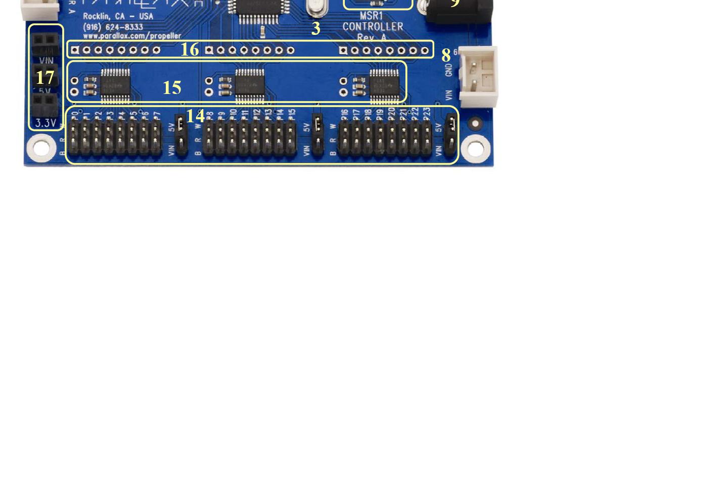
I use the pins 8,9,10 on the PRCB
please look at the attachment prcb_Jumper.jpg
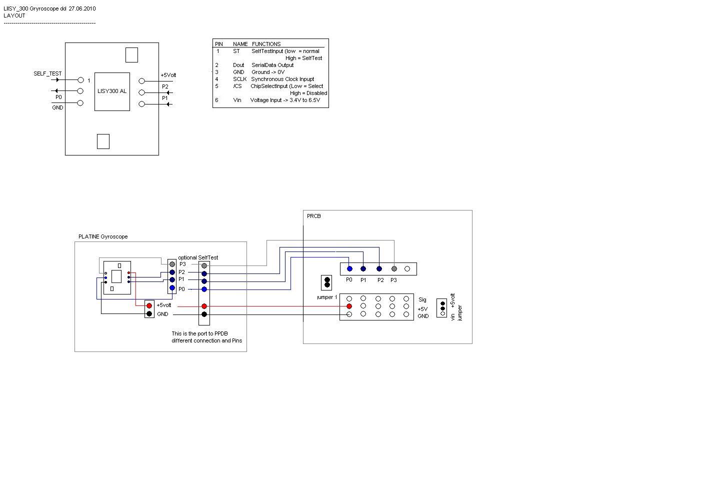
for the Layout of the connection from the sensor to prcb
please look at the attachment: gyroLayout_2.jpg
the prcb_image.jpg look at the interesting sector
for your info:
from the documentation of the LISY-sensor
****************************************************************
Theory of Operation
Internally the LISY300AL Gyroscope generates approximately 1.6V
on its analog output when it is still.
This value is affected very little by temperature so compensation
is not required. The output of the
LISY300AL is fed into a National Semiconductor ADC101S021 10-bit ADC.
This ADC has a high-speed (4 MHz) SPI interface
and the signal pins can operate at 3.3V and 5V.
Both the gyroscope and the ADC are internally regulated to 3.3V.
*****************************************************************
For Hints, Tips and Help i am verry appreciate,
excuse my bad english
Regards
nomad
Attachments:
- prcb_Jumper.jpg
- gyroLayout_2.jpg
Post Edited (nomad) : 6/27/2010 1:55:15 PM GMT
hi,
on the weekend i working with the gyroscope.
i build a little platine (board) for this sensor
and testing this with on the PPDB
All runs are OK
Output OK
on sunday i want connection the gyroscope to the PRCB
(please read my last thread)
on the first test no correct output ADC-value = 0
should be 510
after some test, I have the test again on the PPDB-board
repeated.
results: not correct output
- values
· - adc 0
after a few more testing with the PRCB and gyro-sensor
I had found the correct jumper position
at any rate is the output nothing around 0, but
correspond to the values of ppdb
it's wrong values
· - adc 8191
· - deg1 2879.649
· - deg2 -2699.649
I think the chip is now broken,
and i make a mistake when i set the jumpers
before I buy a new sensor
I want you know if the wiring of the sensors
agrees with the PRCB
I use the pins 8,9,10 on the PRCB
please look at the attachment prcb_Jumper.jpg
for the Layout of the connection from the sensor to prcb
please look at the attachment: gyroLayout_2.jpg
the prcb_image.jpg look at the interesting sector
for your info:
from the documentation of the LISY-sensor
****************************************************************
Theory of Operation
Internally the LISY300AL Gyroscope generates approximately 1.6V
on its analog output when it is still.
This value is affected very little by temperature so compensation
is not required. The output of the
LISY300AL is fed into a National Semiconductor ADC101S021 10-bit ADC.
This ADC has a high-speed (4 MHz) SPI interface
and the signal pins can operate at 3.3V and 5V.
Both the gyroscope and the ADC are internally regulated to 3.3V.
*****************************************************************
For Hints, Tips and Help i am verry appreciate,
excuse my bad english
Regards
nomad
Attachments:
- prcb_Jumper.jpg
- gyroLayout_2.jpg
Post Edited (nomad) : 6/27/2010 1:55:15 PM GMT
1440 x 960 - 89K
1440 x 960 - 71K