

#27922 connection of lisy-Gyroscope to a PropellerRobotControlBoard PRCB
 nomad
Posts: 276
nomad
Posts: 276
Ref. #27922 connection of lisy-Gyroscope to a PropellerRobotControlBoard PRCB
hi,
i want connection the gyroscope to the pins of a PRCB,
but, before i make a burn-out of the sensor,
i have some question about it.
as attachment
(1) gyroLayout_2.jpg
··· is my·layout of the connection the sensor to prcb-board
··· 1) is this layout correct ??
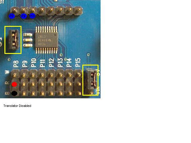
(2) PRCB_IMAGE1.jpg
··· is a part of the official image of a PRCB-Board
··· interesting are the nos.(14) and (16)
for your info:
from the documentation of the LISY-sensor
****************************************************************
Theory of Operation
Internally the LISY300AL Gyroscope generates approximately 1.6V
on its analog output when it is still.
This value is affected very little by temperature so compensation
is not required. The output of the
LISY300AL is fed into a National Semiconductor ADC101S021 10-bit ADC.
This ADC has a high-speed (4 MHz) SPI interface
and the signal pins can operate at 3.3V and 5V.
Both the gyroscope and the ADC are internally regulated to 3.3V.
*****************************************************************
For Hints, Tips and Help i am verry appreciate,
excuse my bad english
Regards
nomad
Attachments:
- gyroLayout_2.jpg
- PRCB_IMAGE1.jpg
hi,
i want connection the gyroscope to the pins of a PRCB,
but, before i make a burn-out of the sensor,
i have some question about it.
as attachment
(1) gyroLayout_2.jpg
··· is my·layout of the connection the sensor to prcb-board
··· 1) is this layout correct ??
(2) PRCB_IMAGE1.jpg
··· is a part of the official image of a PRCB-Board
··· interesting are the nos.(14) and (16)
for your info:
from the documentation of the LISY-sensor
****************************************************************
Theory of Operation
Internally the LISY300AL Gyroscope generates approximately 1.6V
on its analog output when it is still.
This value is affected very little by temperature so compensation
is not required. The output of the
LISY300AL is fed into a National Semiconductor ADC101S021 10-bit ADC.
This ADC has a high-speed (4 MHz) SPI interface
and the signal pins can operate at 3.3V and 5V.
Both the gyroscope and the ADC are internally regulated to 3.3V.
*****************************************************************
For Hints, Tips and Help i am verry appreciate,
excuse my bad english
Regards
nomad
Attachments:
- gyroLayout_2.jpg
- PRCB_IMAGE1.jpg
640 x 480 - 30K
Comments
The instructions are on page 6 of this document:
http://www.parallax.com/Portals/0/Downloads/docs/prod/prop/28230-PropellerRobotControlBrd-v1.0.pdf
Jim
Post Edited (hover1) : 6/25/2010 1:17:55 PM GMT
thank you for your answer.
today on saturday
1) make the platine and soldering
2) tests with PPDB propellerProfessionalDevelopmentBoard
3) if all ok
4) make the stuff with PRCB
5) testing
thank you
regards
nomad
i have done my homework.
the platine (board) is OK
first tests with the PPDB are OK
calculations from ADC to Degrees OK
but I've made the following experiences
1) very unstable ADC values
·· the turns doesn't to reach the maximum of ADC (1024) or
·· the minimum ADC (1)
2)The chip does not tolerate Extension Cable
·· - I have the chip placed on a chicpsocket,
···· could it be that this is the error?
I would be very glad to notice, tips and hints
Tomorrow I will then make that whole stuff with the PRCB
regards
nomad