LED array and with 2 counter modules supplying signals to anode and cathode ser
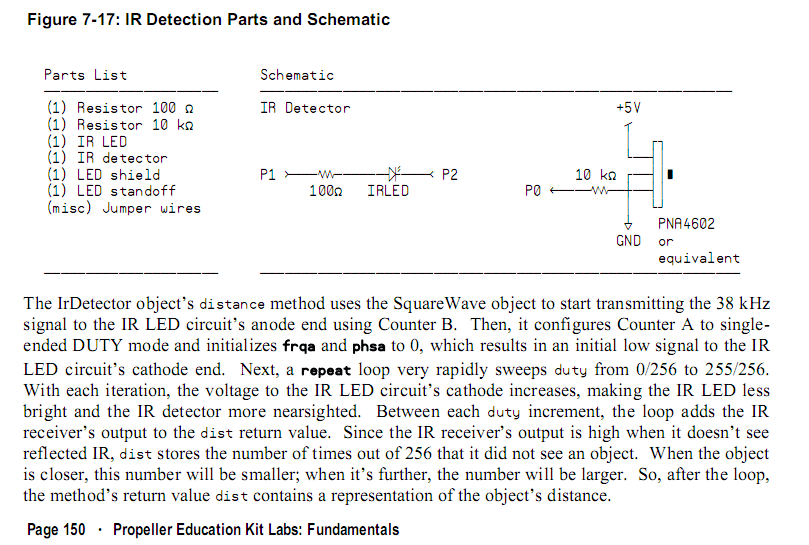
Regarding the Propeller Education Kit Labs manual page page 150 Figure 7-17 (ATTACHED)
http://www.parallax.com/Portals/0/Downloads/docs/prod/prop/PELabsFunBook-v1.1.pdf
A IR LED controlling circuit is presented that uses the SquareWave object to transmitting a 38 kHz
signal to the IR LED circuit’s anode using Counter module B, while a Counter module A is configured to single-
ended DUTY mode that provides for a duty sweep to the IR LED cathode so that distances to objects may be measured
by the resultant signal being detected by a separate IR receiving circuit.
My application requires about 20 IR LED's / receiver pairs. I would like to have all of the 20 IR emitter LED's being controlled by
one circuit (ie. 2 propeller IO pins as in the example circuit) whereby the 20 IR LEDS would be powered by a Darlington transistor Pair (unless there is a better method).
I have not used Darlington Pairs before and my understanding is that one of the Propeller IO pins would supply a small base
current to the Darlington circuit which would provide the Counter module B 38 Khz signal to the lead IR LED anode of the series connected LED's.
The conceptual problem that I have is that if last series LEDs cathode side of the series LED's is connected to the Darlington Pair, then the cathode side Propeller IO pin would be carrying the large series connected LED's current load. How can the cathode side be connected so that the counter module A provides a DUTY sweep the the LED array without the propeller IO pin carrying the large current load?
In advance, thank you for your assistance.


Comments
connected in serial the current would stay the same as with one LED. Disadvantage if one LED fails NO current will flow anymore.
If you connect them parallel the current will increase but the supply-voltage stays the same.
two ideas:
using and AND-gate one input connected to P1 38 kHz the other input connected tp P2 (duty-mode
P1 produces the 38kHz carrier
P2 changes between low and high to make a current flow through the IR-diode.
Another thing to check: Transistor switch slower than logic gates between conductand/non-conductand
I don't remember the frequency of the duty-mode. Maybe this frequency is to HIGH for a transistor.
The duty-frequency has to be high enough to NOT interfere with the 38kHz-carrier but beeing low enough that the transistors can switch
properly
best regards
Stefan
Post Edited (StefanL38) : 6/20/2010 10:10:50 PM GMT