

High frequency IR
 Beau Schwabe
Posts: 6,576
Beau Schwabe
Posts: 6,576
Anyone gone above 40kHz with IR? Way above 40kHz?
With the test I want to do, I need to go up to about 2MHz with IR ... any advice would be greatly appreciated.
With off the shelf components, its difficult to get the frequency up that high. The IR transmitter isn't a problem (according to the datasheet, I should be able to drive it at that frequency), it's the receiver that becomes the problem. An NPN-Phototransistor is ok, but it's only good to about 250kHz. I think what I need is a PN diode. I was looking at the datasheet for the PNZ334 and with a rise/fall time of 4ns that would be 125MHz (way above what I need)
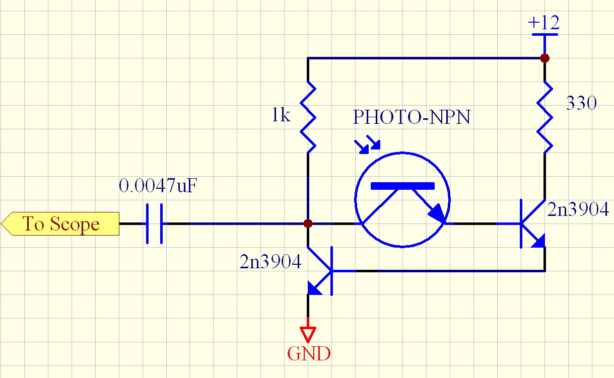
I have attached the receiver circuit that I have been using with the NPN-Phototransistor and even though the datasheet indicates a maximum of 250kHz, I've managed to push it to about 450kHz with the attached circuit. The circuit is a regenerative self biasing circuit similar to the two transistor version of the ZN414. Instead of a Coil/Capacitor tank circuit used to receive AM radio, I have replaced that part of the circuit with the NPN-Phototransistor.
Hopefully with a PN diode, I can use the same circuit as a drop-in replacement for the NPN-Phototransistor.
▔▔▔▔▔▔▔▔▔▔▔▔▔▔▔▔▔▔▔▔▔▔▔▔
Beau Schwabe
IC Layout Engineer
Parallax, Inc.
With the test I want to do, I need to go up to about 2MHz with IR ... any advice would be greatly appreciated.
With off the shelf components, its difficult to get the frequency up that high. The IR transmitter isn't a problem (according to the datasheet, I should be able to drive it at that frequency), it's the receiver that becomes the problem. An NPN-Phototransistor is ok, but it's only good to about 250kHz. I think what I need is a PN diode. I was looking at the datasheet for the PNZ334 and with a rise/fall time of 4ns that would be 125MHz (way above what I need)
I have attached the receiver circuit that I have been using with the NPN-Phototransistor and even though the datasheet indicates a maximum of 250kHz, I've managed to push it to about 450kHz with the attached circuit. The circuit is a regenerative self biasing circuit similar to the two transistor version of the ZN414. Instead of a Coil/Capacitor tank circuit used to receive AM radio, I have replaced that part of the circuit with the NPN-Phototransistor.
Hopefully with a PN diode, I can use the same circuit as a drop-in replacement for the NPN-Phototransistor.
▔▔▔▔▔▔▔▔▔▔▔▔▔▔▔▔▔▔▔▔▔▔▔▔
Beau Schwabe
IC Layout Engineer
Parallax, Inc.
1219 x 751 - 158K
Comments
Fast IrDA is 4 MHz. Maybe one of those receivers could be used ?
Bean
▔▔▔▔▔▔▔▔▔▔▔▔▔▔▔▔▔▔▔▔▔▔▔▔
- - - - - - - - - - - - - - - - - - - - - - - - - - - - - - -
Use BASIC on the Propeller with the speed of assembly language.
PropBASIC thread http://forums.parallax.com/showthread.php?p=867134
March 2010 Nuts and Volts article·http://www.parallax.com/Portals/0/Downloads/docs/cols/nv/prop/col/nvp5.pdf
- - - - - - - - - - - - - - - - - - - - - - - - - - - - - - -
There are two rules in life:
· 1) Never divulge all information
- - - - - - - - - - - - - - - - - - - - - - - - - - - - - - -
If you choose not to decide, you still have made a choice. [noparse][[/noparse]RUSH - Freewill]
Hmmm.. is that frequency fixed, or can it be modulated at something other than 4MHz?
Edit: Never mind... looks like just the Pin Diode ... here is a datasheet I found for one of the 4MHz IrDA devices...
www.datasheetsite.com/extpdf.php?q=http%3A%2F%2Fwww.ortodoxism.ro%2Fdatasheets%2Fvishay%2F81509.pdf
...this one is good up to 5MHz.
I don't know if I will be able to get any of these before the EXPO, so I might (FCC cover your ears) for proof of concept show the RF version.
▔▔▔▔▔▔▔▔▔▔▔▔▔▔▔▔▔▔▔▔▔▔▔▔
Beau Schwabe
IC Layout Engineer
Parallax, Inc.
Post Edited (Beau Schwabe (Parallax)) : 6/18/2010 4:55:42 PM GMT
Try a common-base amplifier. (I think this means that the phototransistor and amplifier will be in a cascode configuration.) The idea is to keep the phototransistor's collector-emitter voltage differential constant (to keep from charging and discharging its Miller capacitance) and convert the current variations to voltage changes. I'm not entirely sure, though, that your circuit does not accomplish the same thing or that 2MHz is even possible with a phototransistor.
-Phil
The Rise/Fall times of a phototransistor don't allow it to go above 250kHz (so the data sheet says)
▔▔▔▔▔▔▔▔▔▔▔▔▔▔▔▔▔▔▔▔▔▔▔▔
Beau Schwabe
IC Layout Engineer
Parallax, Inc.
The TX is simple . Look at the RX systems used In Fiber for a possable solution
Peter KG6LSE
▔▔▔▔▔▔▔▔▔▔▔▔▔▔▔▔▔▔▔▔▔▔▔▔
"Carpe Ducktum" "seize the tape!!"
peterthethinker.com/tesla/Venom/Venom.html
Never underestimate the bandwidth of a station wagon full of tapes hurtling down the highway. —Tanenbaum, Andrew S.
LOL
You need to check the test conditions for that frequency spec. They're typically given for common-emitter mode with a stiff pullup. In a common-base configuration, you might be able to squeeze out more performance. Also, for a modulated waveform, you don't need rail-to-rail transitions. A few tens of millivolts would be enough.
-Phil
Here's a circuit I used to test the common base idea:
The inductor is a choke I got from RadioShack. I have no idea what the value is. The cap, in conjunction with the inductor, apparently provides a resonant tank circuit. The resistor helps to lower the Q (I guess -- still learning this stuff) and quences the ringing I observed without it. I'm sure someone who knows what they're doing could tune this for an even better response.
Here's the response I got from an IRED in close proximity to the phototransistor:
Of the 212mV amplitude, 72mV is electrical feedthrough (since I used the same solderless breadboard for both transmit and receive) and 140mV was the actual photoresponse. This was verified by shielding the phototransistor with an opaque plastic cap.
BTW, the phototransistor I used is an MRD701, which specs 10us turn-on and 60us turn-off times.
The output from this circuit would be a good match for my Propeller AM receiver object.
-Phil