

Strain gage amplification
 FredBlais
Posts: 395
FredBlais
Posts: 395
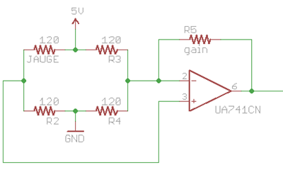
Hi guys, I've been spending the last days trying to make a reliable sensor. I glued·a 120 ohm strain gage on a pair of pliers. What I want to do is to determine the opening of the pliers according to the reading on a wheatstone bridge. I attached a picture of the circuit.
I used a cheap uA741 from ST for the opamp. When the pliers are fully opened and fully closed I have a range of 3mV. After setting the right amount of gain and setting the zero bias, I can have a reading that go from 1.8V to 4.3V. So everything seems to work better than expected.
The problem is that 1-2 hours after setting the bias, the reading have drifted and the op-amp saturates, so I have to repeat the calibrating steps again and again. So is it the resistors value with temperature? is it the op-amp that drifted? I don't have a clue...
I'm waiting for some·more·advanced op-amps and instrumentation op-amps samples that I ordered from Linear Technology claiming low drift and offset voltage.
Anybody has some experience with strain gage, op-amps·or bridge amplification? I always seems to have trouble with analog circuitry...
400 x 250 - 17K
Comments
I have had some experience with strain gages so perhaps I can help.
My first suggestion is that, if you are using only a single gage in the wheatstone bridge circuit the other three resistors must be ultrastable. This is because the gage is going to change resistance due to metallic strain by only a few percent. So, resistance in the other arms of the bridge must not change at all! That is one reason gages are used on all four arms of the bridge on commerical load cells [noparse][[/noparse]the other active arms also increase the output due to strain.].
Go for the instrumentation amplifier too. They are inexpensive and offer many attributes. I use the INA 125.
I can go on, but please keep experimenting and keep us posted. Gages make very useful sensors.
cheers, David
Let me recommend two sites which may be of help:
http://www.jamesyawn.com/electronicstand/amp/board2.html
http://www.vishaypg.com/micro-measurements/
Here is some insight into the [noparse][[/noparse]small] amount of output from a strain gage bridge.
[noparse][[/noparse]Note: Please check my arithmetic.]
Your pliers are probably made of steel. Steel has a modulus of elasticity [noparse][[/noparse]E] of roughly 29
million psi. This means that in order for the pliers to elongate or compress to 100% [noparse][[/noparse]100%
strain] of it's original dimension, the stress must become 29 million psi. No such stress is
possible. First, it would break long before. Moreover, to stay within it's elastic limit [noparse][[/noparse]where the
pliers would return to it's original state after the load was removed] the stress must be less than,
say, some 30 thousand. And in more normal usage the stress would probably be far less; say 3
thousand psi.
3 thousand psi equates to a measured strain of:
E = stress/strain or,
strain = stress/E = 3000/29,000,000 or roughly 1/10,000 [noparse][[/noparse]n.b. strain is dimensionless.]
Thus the strain measured by the gage is on the order of 100 microstrain !!
The gage probably has a Gage Factor of 2 [noparse][[/noparse]the % gage change = 2x the % strain].
Using the calculator from the following site, and inputting 100 microstrain:
http://www.vishaypg.com/micro-measurements/stress-analysis-strain-
gages/calculators/tn/tn507/507bo1j.htm
The output from a single active gage bridge is on the order of 0.0500 mV/V.
[noparse][[/noparse]note: Commerical load cells would have an output of some 3.0 mV/V. They use a 4 active arm
bridge; with the gages placed in optimum, maximum strain, positions.]
Say the 120 ohm gage bridge can be safely supplied with 5 Volts*. The strained output is some
0.25 millivolts !! Hence the need for amplification; and bridge balancing circuitry.
* The bridge voltage limit is based on the electrical heating the gage can handle without
affecting it's output. There is a calculator for heat density too:
http://www.vishaypg.com/micro-measurements/stress-analysis-strain-
gages/calculators/tn/tn502/502eqabj.htm
This is then coupled with recommendations for maximum allowable heat density:
http://www.vishaypg.com/docs/11052/tn502.pdf
Enough?
Thanks a lot dre for your input, the INA125 seems like a great one chip solution, I will try it and give you feedback. Do you think that the drifting problem may be eliminated? Let's say, if no strain is applied and I have 2.5 volts the value will be the same 1 week later?
A week with minimum drift is, I think, asking a lot. You can test the electrical portion of
the system by shorting the inputs to one another.
Using precision, equal value resistors are necessary for long term stability. Unfortunately
they are about as expensive as gages. And gages [noparse][[/noparse]and completely bridged load cells] can
be found on e-bay. You could cement the gages to a dummy piece of metal and use 1 or
all to complete your bridge.
I don't know what you mean by having 2.5 volts? Is this the supply to the bridge? I hope it
is not the output from the bridge as this would indicate a severe unbalance. Unbalance
will show up in any strain gage bridge due to tolerances in even 1% resistors when the
output is amplified. I always have to include a balancing circuit; which is a 10 turn or
better pot between, say, the + and [noparse][[/noparse]-] of the bridge supply voltage; with the wiper
terminal connected to either the + or [noparse][[/noparse]-] output of the bridge. A balancing limiting
resistor is generally placed in this connection [noparse][[/noparse]between the wiper and the + or [noparse][[/noparse]-] bridge
output] so you don't accidently short out one arm by driving the balancing pot to one end.
The balancing pot can be of some value much higher than the gage resistance. Say 50k to
200k ohms. The limit resistor can be about 1/10 of the pot value.
I don't know how to provide a drawing but note figure [noparse][[/noparse]5d] on page 17 of:
http://soliton.ae.gatech.edu/people/jcraig/classes/ae3145/Lab2/strain-gages.pdf
cheers, David
Yes. The load is too much for the regulator within the chip; especially for your 120, low ohm bridge. I use the TIP transistor circuit as shown in figure 4 of the INA125 datasheet. I have used any one of many NPN TIPs. Radio Shack probably even has one.
The drift should be much lower using the INA. Make sure your connections between bridge arms and into the ampl. are solid.
Don't despair if you can't get the bridge to balance initially. You may have to shunt one arm to achieve balance. Try not to use the gage arm as this makes the gage reading less sensitive. If you have a 200mV range digital meter try getting close to balance by nulling out any voltage between the + & [noparse][[/noparse]-] bridge outputs [noparse][[/noparse]the amplifier inputs]. This will at least get you into the ballpark. Remember, you have to use a high amplification and this makes balancing difficult.
I am off on a north country 'canoeing' trip for about 2 1/2 weeks. Will have a laptop but don't know about a connection at the lodge. Will try to check in occasionally.
cheers, David
Hi,
Glad you are having success with your gage installation. Another possible source of drift is the gage adhesion. If this is suspected there is an 'eraser' test which will detect a·problem with·gage installation. I can describe this if desired.
Finally, in the way of some strain gage humor: Wikipedia "strain gage" and find out about the association to the origin of 'Murphy's Law'. Hint: the mistake is easily explained.
Feel free to keep in touch if I can be of any further help.
cheers, David