

Questions regarding current on pins
 johnnycarlos
Posts: 44
johnnycarlos
Posts: 44
Hi Folks,
I am trying to determine when and if resistors are required on Propeller chip pins. The description says they can "sink/source 40mA at 3.3 Volts". During output, does that mean the chip can manage its own current and will limit it to 40mA, or do I need to use Ohm's Law to determine a minimum resistor value( 3.3V/.04 A )?
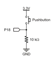
On the input side, what is the purpose of a resistor in parallel to the pins? (see attachment)
Any suggestions appreciated.
Thanks!
John
I am trying to determine when and if resistors are required on Propeller chip pins. The description says they can "sink/source 40mA at 3.3 Volts". During output, does that mean the chip can manage its own current and will limit it to 40mA, or do I need to use Ohm's Law to determine a minimum resistor value( 3.3V/.04 A )?
On the input side, what is the purpose of a resistor in parallel to the pins? (see attachment)
Any suggestions appreciated.
Thanks!
John
194 x 214 - 9K
Comments
If the pin is an input, referring to your attached diagram, the resistor is there to pull the pin low when the switch is open. Otherwise the pin is floating and there are no guarantees as to what you will get if you read it (pushbutton open). There may be internal pull up or down resistors in the prop (I don't know) but as a rule it is good practice not to leave it to chance.
As an aside, it is sometimes a good idea to add a resistor in series with the pin, to limit the current in the event of accidentally misconfiguring the pin as an output.
Cheers,
Mark
I did some searching on how to determine the base current of a transistor so I could use it as a switch. Here is what I used:
R1 = Supply Voltage / ( Maximum Current Required / Minimum HFE * 1.3 )
I put in the proper resistor for that current(which also happened to be less than 40mA) and it works. And the numbers observed on my meter check out perfectly with the calculations. I love it when a plan comes together.
Thank you.
John
The 1.3 may be a fudge factor to over compensate and ensure saturation but then that needs to be more like:
R1 = (Supply Voltage - 0.6V ) / ( ( Maximum Current Required / Minimum HFE ) * 1.3 )
So calculating an example:
R1 = 3.3 - 0.6 / ( ( 100ma / 100 ) * 1.3 )
R1 = 2.7 / 1.3ma ----> round down to 1K8 at least and I would just use 1K.
▔▔▔▔▔▔▔▔▔▔▔▔▔▔▔▔▔▔▔▔▔▔▔▔
*Peter*
I really appreciate everyone's help.
John