

Controler problem with Hippo balance bot

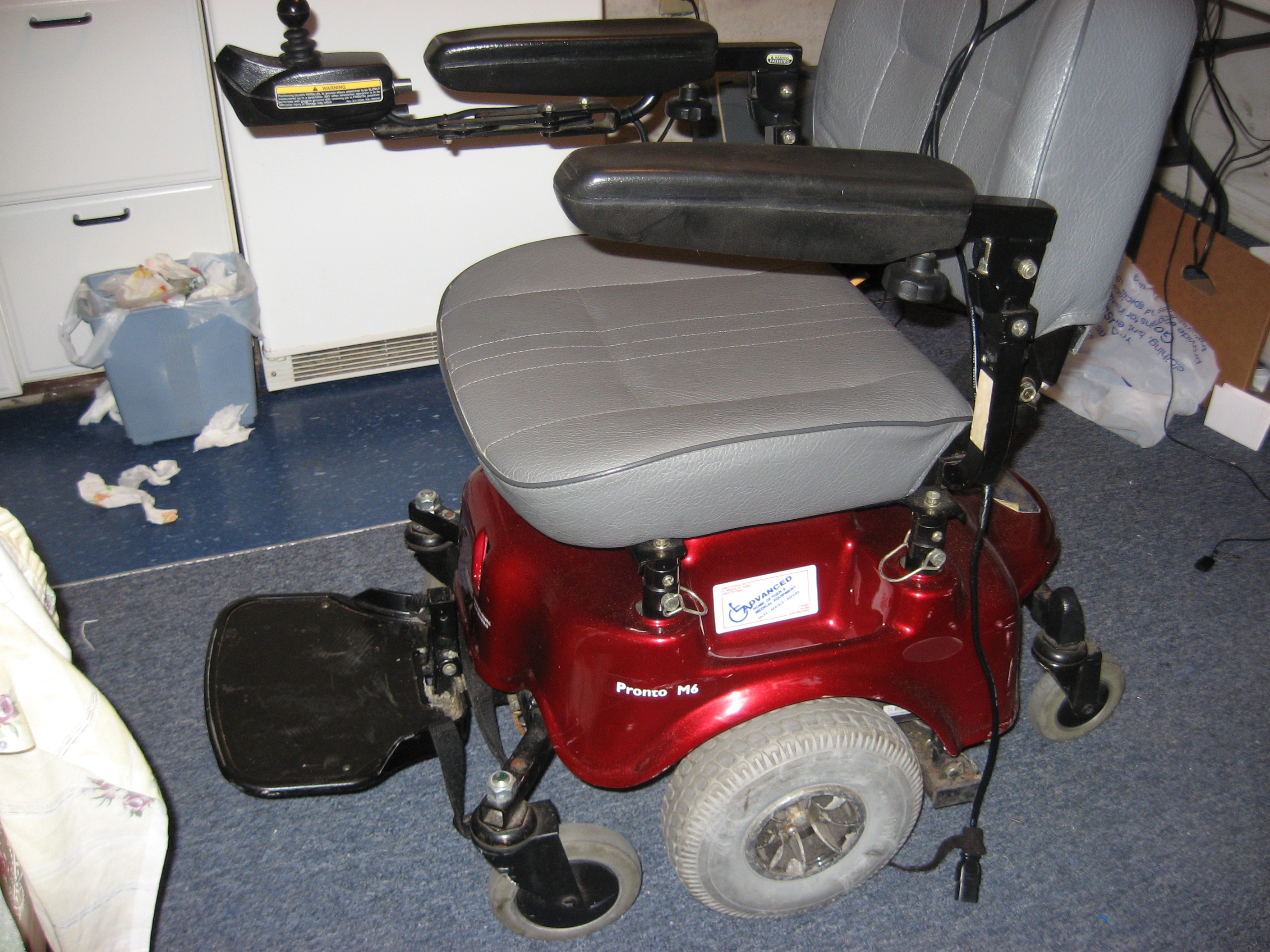
At the homeless shelter we get some interesting donations. Awhile back a powered hospital bed came in. We took it to the local medical supply and traded it for a 20 year old power wheelchair. Nice 24volt system that works great. Might make a nice Segway type (100 lb!) balance bot.
To make a long story short we hacked the joystick to see what controls it.
Behold, it seems to be an analog signal.
Forward sends 4.5vac to the motor controller.
Reverse sends 1vac on the same wire. At rest in center is 2.5vac.
Ditto for the left-right-center signal wire.
Don’t have a scope to see what we’re really looking at nor are schematics available.
Any ideas how to “basic stamp2” this thing?
Gramps
▔▔▔▔▔▔▔▔▔▔▔▔▔▔▔▔▔▔▔▔▔▔▔▔
'What is your life?"
"It is even a vapor that appears for a
little time and then vanishes away."
Saint James 61 A.D.
Post Edited (Gramps) : 6/11/2010 10:57:02 PM GMT
2816 x 2112 - 2M
Comments
http://www.rentascooter.com/downloads/_manuals/invacare/Invacare Pronto M6 Owner's Manual.pdf
The following service manual may some wiring/schematic/technical info. It's not the same model but it is the same series. The existing controller seems to be somewhere around 80amps. If you can find a model number/manufacturer on the existing motor controller, you should be able to Google specs and a control signal format for it:
http://www.rentascooter.com/downloads/_manuals/invacare/Invacare Pronto M91 and M94 Service Manual.pdf
If you want to run the Invacare chair from a Stamp, you'll need some very hefty motor controllers or will need to hack into the existing controller. Then it wouldn't be too much different than driving servos.
One thing I would strongly encourage is an easy to find "kill" switch for the motors. I've built several large, heavy robots -- once they are moving they *really* can hurt and do damage when performing unexpected maneuvers during debugging
It can be useful to kill the motors (without shutting down all the electronics) in such cases, and for testing things like obstacle avoidance systems while keeping the platform stationary.
▔▔▔▔▔▔▔▔▔▔▔▔▔▔▔▔▔▔▔▔▔▔▔▔
When the going gets weird, the weird turn pro. -- HST
1uffakind.com/robots/povBitMapBuilder.php
1uffakind.com/robots/resistorLadder.php
Post Edited (Zoot) : 6/12/2010 2:18:06 AM GMT
Yup.
http://forums.parallax.com/showthread.php?p=908122
Rich H
▔▔▔▔▔▔▔▔▔▔▔▔▔▔▔▔▔▔▔▔▔▔▔▔
The Simple Servo Tester, a kit from Gadget Gangster.
Zoot, Thanks for the information. I did try to track the model number but to no avail.
Yes, the kill switch is a very good idea. Just playing around with the handheld almost ran myself down!
Any tried and true methods you can suggest that work well?
Rich, you have the answer! Why reinvent the wheel? Can you sell me one?
I’m still not clear about how this handheld controls the controller. Please educate me.
P.S. The true age of this beast looks more like 30+ years!
Gramps
▔▔▔▔▔▔▔▔▔▔▔▔▔▔▔▔▔▔▔▔▔▔▔▔
'What is your life?"
"It is even a vapor that appears for a
little time and then vanishes away."
Saint James 61 A.D.
The kill switch is just that -- brute force. You would want the switch on the cable from the battery to the motor controller. Simple on/off. The only hitch is the high amps. Automotive switches (heavy duty rockers and the like) can often be found that may cover you. Also solar PV companies sell a lot of high-amp DC products (here's a battery switch rated to ~300amps: http://www.affordable-solar.com/perko-dc-battery-switch.htm).
W9GFO's little board is meant to replace the POTS in the joystick -- the variable resistors -- basically you would cut the wires to the pots and splice in that board. I presume the small micro on his board is set to receive serial or pulse commands, it then uses the on-board digital pots to "mimic" what would be joystick settings. Very clever. You don't need a standalone board necessarily, though. You could pick up two digital pots and use SHIFTOUT on the Stamp to control them. It might be the safest and cheapest and easiest way of running the platform, and since you wouldn't have hacked into the controller or main control harness, you could easily put a regular joystick back into the chair if you ever wanted to "de-robo-fy" it.
▔▔▔▔▔▔▔▔▔▔▔▔▔▔▔▔▔▔▔▔▔▔▔▔
When the going gets weird, the weird turn pro. -- HST
1uffakind.com/robots/povBitMapBuilder.php
1uffakind.com/robots/resistorLadder.php
the controller # is:
INVACARE MKIV-R11 Controller
Yes to use digital pots was my first thought. Wasn't getting resistance readings on the joystick, but voltage.
So I'll have to hack a little deeper to find the pots in the little joystick module.
▔▔▔▔▔▔▔▔▔▔▔▔▔▔▔▔▔▔▔▔▔▔▔▔
'What is your life?"
"It is even a vapor that appears for a
little time and then vanishes away."
Saint James 61 A.D.
Rich H
▔▔▔▔▔▔▔▔▔▔▔▔▔▔▔▔▔▔▔▔▔▔▔▔
The Simple Servo Tester, a kit from Gadget Gangster.
Rich H
▔▔▔▔▔▔▔▔▔▔▔▔▔▔▔▔▔▔▔▔▔▔▔▔
The Simple Servo Tester, a kit from Gadget Gangster.
Yes, mine has 4 wires also.
Sent you my address.
Sure appreciate your help!
Gramps
▔▔▔▔▔▔▔▔▔▔▔▔▔▔▔▔▔▔▔▔▔▔▔▔
'What is your life?"
"It is even a vapor that appears for a
little time and then vanishes away."
Saint James 61 A.D.