

How to limit voltage extremes on PWM
 T Chap
Posts: 4,260
T Chap
Posts: 4,260
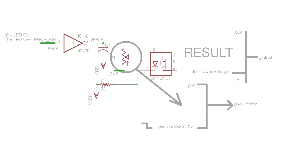
I am stuck on how to do this. The obvious first thought was to use a trim pot as shown in the drawing, I put the trim pot in the drawing just for a visual. The idea is, I want to be able to set a maximum volume level on a line level audio path using the Opto Jfet to pull the level down, this serves several purposes, as the fet can be ramped up or down to prevent pops, hard switching is too abrupt for the application and I want programmable ramp times. So the goal is to use a trim pot (or 8 bit ladder) as a master volume that controls several jfets at once, using a scheme where the input to the LED has a lower level limit, meaning that at 3v3 the audio if fully muted as the jfet is effectively shorting the audio path the GND before it sees an audio amp down the line. When the LED is seeing 0vdc, then the jfet is doing nothing to the audio, the audio is at max volume. I want to limit the max volume by setting a limit to the lower level voltage derived from either PWM or logic low so it never hits 0, but can sit where it needs for the project. This way, there is a single fixed lower level limiter that can affect multiple fets.
The trim pot is the right idea for a starting point, but it is not ideal, as there is loss of current, but the trim pot does seem to work as long as you park the wiper at one extreme or the other. Can anyone suggest a better way to accomplish limiting the lower extreme of PWM or logic 0 without affecting the high side(3v3)?
The trim pot is the right idea for a starting point, but it is not ideal, as there is loss of current, but the trim pot does seem to work as long as you park the wiper at one extreme or the other. Can anyone suggest a better way to accomplish limiting the lower extreme of PWM or logic 0 without affecting the high side(3v3)?
992 x 512 - 46K
Comments
This may not be the case however and so what you really need to do then is run the Prop to an RC filter and then buffer it with a simple NPN emitter follower to supply the led current. You will not get the full range of PWM though because anything below the led forward voltage drop (around 1.2V) will not work. Also, the response of the led and JFET combo may not be linear.
▔▔▔▔▔▔▔▔▔▔▔▔▔▔▔▔▔▔▔▔▔▔▔▔
*Peter*
Since the led is a current device you could drive in a fashion that overcomes the forward bias required. Using the NPN as an emitter follower but placing the led in series with the collector and supply you effectively have created a voltage to current converter (and buffer). The current is set simply as V/R where V is the PWM voltage less 0.6V base-emitter drop and R is the emitter resistor. Please note that you do not use the 180R resistor at all as the NPN+R becomes the constant current source. For 20ma full current you would say that R=V/I where V = 3.3-0.6 = 2.7 so 2.7/0.02 = 135R so a value of 120R would be good for starters.
EDIT: The base-emitter has some resistance too but 120R or even 100R is still good for starters.
▔▔▔▔▔▔▔▔▔▔▔▔▔▔▔▔▔▔▔▔▔▔▔▔
*Peter*
Post Edited (Peter Jakacki) : 6/6/2010 1:12:09 AM GMT
"... meaning that at 3v3 the audio if fully muted as the jfet is effectively shorting the audio path the GND before it sees an audio amp down the line. When the LED is seeing 0vdc, then the jfet is doing nothing to the audio, the audio is at max volume ..."
You sure?
a J-fet should be 'ON' without power applied. When you apply power is when it turns 'OFF'.
If your device turns 'ON' with power, then it is a MOSFET, in which case you need two of them in series back -to-back to negate the internal reverse diode.
back-to-back implies that both Drains are tied together so that one Source goes to GND and the other Source goes to the 1K resistor as you have it in one of your other schematics.
▔▔▔▔▔▔▔▔▔▔▔▔▔▔▔▔▔▔▔▔▔▔▔▔
Beau Schwabe
IC Layout Engineer
Parallax, Inc.
Post Edited (Beau Schwabe (Parallax)) : 6/6/2010 4:54:40 AM GMT
to add to Beau: there is 2 kinds of MOSFETS ...
Enhancement mode and Depletion mode .
both are opposite of each other [noparse]:)[/noparse]
Peter KG6LSE
▔▔▔▔▔▔▔▔▔▔▔▔▔▔▔▔▔▔▔▔▔▔▔▔
"Carpe Ducktum" "seize the tape!!"
peterthethinker.com/tesla/Venom/Venom.html
Never underestimate the bandwidth of a station wagon full of tapes hurtling down the highway. —Tanenbaum, Andrew S.
LOL
I thought it was a Jfet, but is a Photo FET H11F1M When you turn on the LED, it acts just like a variable resistor and drops to about 100ohm, basically open with no voltage. I will post the working schematic later.
Post Edited (Todd Chapman) : 6/6/2010 6:38:36 AM GMT
This could be use for a crude DA with no cogs or resources required to set a voltage anywhere you want and leave it alone after it is set. The nice thing about the 8 counters on the Prop are that you have 8 DAC's that can run behind the scenes forever until you change them.
CON
  _clkmode               = xtal1 + pll16x
  _xinfreq               = 5_000_000


obj

VAR
  long rate, x, y, volmax

PUB Start
  Y := 1_000_000_000   'start muted
  DAC_START(13, y)
  dira[noparse][[/noparse]13] := 1

  SetVol(100)  '% max vol  0 = off  100 = max
  'testing
  repeat
    'FadeIn
    'waitcnt(80_000_000 + cnt)
    'SetVol(10)
    'waitcnt(80_000_000 + cnt)
    'FadeOut
    'SetVol(100)
    'waitcnt(80_000_000 + cnt)

PUB SetVol(mult)
    Y := 1_000_000_0  * (100 - mult)
    DAC(y)


PUB FadeIn
   volmax :=  1_000_000_00
   Y := 1_000_000_000
   rate := 50000
   DAC_START(13, y)
   dira[noparse][[/noparse]13] := 1
   DAC(y)
   REPEAT while Y > volmax
     Y :=  Y - rate
     DAC(y)
     waitcnt(40_00 + cnt)
   'REPEAT


PUB FadeOut
   volmax :=  1_000_000_000
   'Y := 1_000_000_00
   rate := 20000
   REPEAT while Y < volmax
     Y :=  Y + rate
     DAC(y)
     waitcnt(40_00 + cnt)
   'REPEAT


PUB DAC_START(PIN, freq)
    ctra := %00110 << 26 +  pin

PUB DAC(Value)
    frqa := value

PUB DAC_STOP(PIN)
    ctra := %00000 << 26' +  pin
Post Edited (Todd Chapman) : 6/6/2010 8:34:29 AM GMT
If your control voltage is common to both channels you can put both optos in series using a single NPN. I have attached a sample schematic to show how I might hook it up. Notice that the RC circuit is driven directly from the Prop and that there is a separate 10K pullup which makes sure that the opto is fully on when the I/O is still not set.
Yes, using duty-mode output from the counters (2 per cog = 16) is a better way of generating a voltage.
TIP: Do you know that if you use an amp like the TDA7052 in place of the LM386 that you can get more power at +5V into the speakers and without all those bulky coupling and compensation capacitors.
EDIT: returning the optos to a higher voltage than VDD would be beneficial as the current source would drop 2.7V max and the optos around 1.2V each so even +5V would be good.
▔▔▔▔▔▔▔▔▔▔▔▔▔▔▔▔▔▔▔▔▔▔▔▔
*Peter*
Post Edited (Peter Jakacki) : 6/6/2010 9:18:35 AM GMT
1. The IRED's Vfwd(max) is 1.75V. If Vdd is 3.3V, it's not high enough to have the IREDs in series. (Even driving them from 5V is not enough, given the 1.6V emitter voltage at 16mA.).)
2. The base and pullup resistor values are too high to drive the transistor adequately. For an IRED current of 16mA, the emitter resistor must have 1.6V on it, which means the base has to be driven at 2.2V. With a 3.3V drive through the two 10K resistors (on reset), that's only 55uA of base current. The transistor would have to have a minimum current gain of about 300 for this to be effective, which is much higher than that of the 2N3904.
I'd be more incliined to use the isolator in series mode to pass the audio, rather than shunt mode to choke it. That way the audio will pass only when the IREDs are being driven, precluding any special treatment when the Prop pin is not being driven. Also, the optos' switching time is around 25usec, which is pretty slow. So you may not even need the cap, if you use a DUTY mode output to drive the transistor.
-Phil
Running the audio with the isolator in series is doable, I tried lots of combinations of shunt and series, and spent all night just trying to solve the aliasing noise which was present both modes until I changed from .1 to 1uF, and just happened to be in shunt when it got resolved. I am using Duty and find that there are strange noise artifacts without it. Testing NCO there was no frequency that worked for audio. Keep in mind that I am not using any methods to keep the phsa resetting as would be required for PWM, basically just setting the clock freq and letting it run, unless it is time to ramp it up or down, then a method handles that and parks it again.
Using 5v then the series resister to GND and to the base are fine.
Post Edited (Todd Chapman) : 6/6/2010 6:07:01 PM GMT
▔▔▔▔▔▔▔▔▔▔▔▔▔▔▔▔▔▔▔▔▔▔▔▔
*Peter*
I really appreciate the detailed responses. I went through all the notes today and have it working really nicely. I don't have the TDA7052a amps yet but tested on several hi fi systems. These optofets sure make for a cheap method to control audio without having to have dual supplies and other expensive parts. Below are the final drawings and test code. The base has a weak pullup for poweron which keeps things muted until something else takes over. The audio did not sound right using the fet in series (consumer CD player line out). The shunt works well with a 100k resister in series and shorting the amp side, without the series R the audio sounds bad between the extremes of full on and full off, in between it gets distorted for some unknown reason.
CON
  _clkmode               = xtal1 + pll16x
  _xinfreq               = 5_000_000

VAR
  long rate, x, y, volmax

PUB Start
  Y := 2_147_000_000   'start muted 2_147_000_000 = MUTED  0 = Unmuted
  DAC_START(13, y)
  dira[noparse][[/noparse]13] := 1
  repeat   'tests
    FadeIn
    waitcnt(80_000_000 + cnt)
    FadeOut
    waitcnt(80_000_000 + cnt)

PUB SetVol(val)    '2_147_000_000 = MUTED  0 = Unmuted
    Y := val
    DAC(y)


PUB FadeIn
   volmax :=  0
   Y := 2_147_000_000
   rate := 50000
   REPEAT while Y > volmax
     Y :=  Y - rate
     DAC(y)
     waitcnt(40_0 + cnt)

PUB FadeOut
   volmax :=  2_147_000_000
   Y := 0
   rate := 30000
   REPEAT while Y < volmax
     Y :=  Y + rate
     DAC(y)
     waitcnt(40_00 + cnt)

PUB DAC_START(PIN, freq)
    ctra := %00110 << 26 +  pin
    frqa := freq

PUB DAC(Value)
    frqa := value

PUB DAC_STOP(PIN)
    ctra := %00000 << 26' +  pin
Post Edited (Todd Chapman) : 6/7/2010 4:47:44 AM GMT
The 1uf appears as a dead-short to anything but DC from the Prop plus it will discharge as quickly as it charges, not what you want. Use the 1K from the Prop to charge the capacitor which BTW can now be a much smaller value. The output of this RC filter is fed straight into the base of the NPN without any other current limit resistors required as the input resistance of this is around gain*(Re+100) which is at least 12.5K.
▔▔▔▔▔▔▔▔▔▔▔▔▔▔▔▔▔▔▔▔▔▔▔▔
*Peter*
What happens if you remove C5? The reason I'm asking is that it's probably not serving any purpose without some series resistance from the Prop pin. Moreover, driving a cap that large without the series resistance could result in pin failure, due to the large switching currents.
-Phil
Post Edited (Todd Chapman) : 6/7/2010 6:12:10 AM GMT
Come on, why would you want to short it to ground? The whole idea of a BTL (bridge tied load) amp is to drive the speaker differentially so you need 2 outputs without a ground. If you were to try to drive the speaker single ended then you would need a big capacitor to couple the AC and block the large DC that would otherwise flow but that's what the LM386 does already.
▔▔▔▔▔▔▔▔▔▔▔▔▔▔▔▔▔▔▔▔▔▔▔▔
*Peter*
The BTL amps are best for driving speakers but line outputs need to be single-ended though low power and headphones usually have a common but they can be driven by a much simpler stereo headphone amp.
EDIT: You should be able to drive each side of the headphones with the single ended output of the BTL amp but coupled through a small capacitor. Should work.
▔▔▔▔▔▔▔▔▔▔▔▔▔▔▔▔▔▔▔▔▔▔▔▔
*Peter*