

Request For Comments - Schematic for Prop Based Bicycle Navigation
 LarryG
Posts: 50
LarryG
Posts: 50
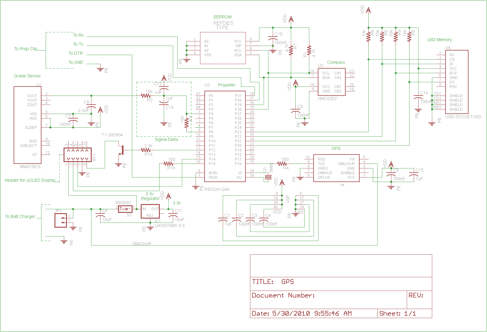
My first Propeller project is a bicycle navigation system. Some of my rides can be somewhat long (200+ miles) and it helps to know where I am going. Most of the building blocks have been fully tested individually on my Prop Demo Board. I thought I might as well dive in head first; learning how to use Eagle (I almost dusted off my old drafting table in the process), learning how to solder SMD (bought my first pre-heater and air re-work station), and basically updating my 30 year old skills.
The bicycle nav does the following:
-GPS constantly calculates the direction and distance to home, as well as altitude
-Accelerometer gives me the percent grade of the road (with help from the Propeller, of course)
-Compass module helps me reference North for more help finding my way around
-Future- hope to do data logging for GPS so I can upload my rides to Google and map them out
Before I layout the board in Eagle, I was hoping to get comments on my schematic. It is my first attempt at Eagle, and I am sure I made some mistakes. If anyone would be kind enough to take a look at the attached and offer comments, I would be very grateful. I am including both PNG and SCH files of the same schematic. I know you cannot comment on specifics without having the specs of each component. I am mostly looking for errors I might have made, like shorting out VDD and GND, maybe not wiring the EEPROM to the Propeller correctly, stuff like that.
My next posting, hopefully in a week or so, will then be the design of the circuit board (mostly SMD).
Thanks for any feedback.
Edit 10:00 EST - Made changes to schematic based on feedback from MagIO. Removed series resistors for uSD card, attached DO line. New rev now attached.
-Larry G.
Post Edited (LarryG) : 5/30/2010 2:01:23 PM GMT
1609 x 1098 - 37K

Comments
something similar but ran out of cogs. I think it is still possible with one chip but I really got to tighten things up.
-Data logging is a future option. If I run out of cogs, then I forgo data logging
-I really mostly need the compass to work when I am at a standstill. This is because the GPS only gives heading as you are moving. Maybe I unload the sigma-delta cog when it sees I am not moving, and load the compass object. I don't care to know the grade of the road while I am not moving.
I would be interested in hearing more about your project.
Thanks.
Larry G.
What about the ENABLE pin of the GPS?
Enable on my GPS can float. Pull down to disable the GPS. Manual says OK to float.
Thanks for catching that DO line for me.
Larry G.
▔▔▔▔▔▔▔▔▔▔▔▔▔▔▔▔▔▔▔▔▔▔▔▔
Jon McPhalen
Hollywood, CA
Thanks.
Thanks.
-LarryG
A quote from the expessPCB website:
"When placing narrow traces, 0.012" or less, avoid sharp right angle turns. The problem here is that in the board manufacturing process, the outside corner can be etched a little more narrow. The solution is to use two 45 degree bends with a short leg in between."
Others might comment on high freq signals not liking 90 turns, but I can't comment on that.
Jim
Post Edited (hover1) : 6/23/2010 12:16:46 AM GMT
I don't know what data you plan to display with the OLED, but it can be hard to read OLED's outdoors. If you just need compass and distance, there are plenty of options, but they won't look as cool as a little OLED. Personally, I would just use an audio announcement - when you push a button, a small speaker tells you what direction you're traveling and how far from home. It would also alert you if you had GPS problems.
Overall, I think it's a good project - not too hard but still rewarding. There are plenty of objects in the Obex to help you along the way, too.
▔▔▔▔▔▔▔▔▔▔▔▔▔▔▔▔▔▔▔▔▔▔▔▔
Propeller Forums RSS Feed!
Gadget Gangster - Share your Electronic Projects
Thats good advice, my software always puts in angled bends and I never knew why.
Thanks for the heads up.
Ditto the 90-degree comments. You need to distribute your bypass capacitance around the Prop chip a little better. Two caps on opposite sides is the minimum. I'd also include a pour area on the top side under the chip for Vdd. And make your supply lines fatter.
-Phil
▔▔▔▔▔▔▔▔▔▔▔▔▔▔▔▔▔▔▔▔▔▔▔▔
Links to other interesting threads:
· Home of the MultiBladeProps: TriBlade,·RamBlade,·SixBlade, website
· Single Board Computer:·3 Propeller ICs·and a·TriBladeProp board (ZiCog Z80 Emulator)
· Prop Tools under Development or Completed (Index)
· Emulators: CPUs Z80 etc; Micros Altair etc;· Terminals·VT100 etc; (Index) ZiCog (Z80) , MoCog (6809)·
· Prop OS: SphinxOS·, PropDos , PropCmd··· Search the Propeller forums·(uses advanced Google search)
My cruising website is: ·www.bluemagic.biz·· MultiBlade Props: www.cluso.bluemagic.biz
▔▔▔▔▔▔▔▔▔▔▔▔▔▔▔▔▔▔▔▔▔▔▔▔
90 * 2 = Pi
@pi'd - I would be interested if you have any suggestions for a graphic LCD that is easy to use. I picked the 4D Systems because it supports commands like "draw a circle". I wish they had the same product in LCD. It would save a ton of power and to your point have much better contrast.
@Cluso99- Thanks, I am now in the process of re-positioning caps for regulator.
@Phil and Hover1 - I am changing all 90 degree bends. I did not know it was that critical, but it sounds like it is.
@Nick - I have not played with gyros yet. But I am pretty familiar with accelerometers, and have some pretty good success at measuring static incline with them. Thanks for your other comments and encouraging words.
Newly designed board should be posted later this week. I am getting anxious to get this thing made. It has been a long journey.
Thanks to all.
Larry
I don't know where you ride but here there are some very punishing hills.
One thing you might consider to add is an atmospheric pressure transducer.
GPS is almost useless for altitude. The pressure transducer should help your determine the elevations you had negotiated on your ride.
I have thought of doing something like this with my "On screen Drone" project.
Good luck
Perry
I looked into the Hill Hundred. Looks pretty challenging, almost 4,000 ft of climbing. We have some hills around here, but we have to really search them out and string them together to make a challenge.
-Larry