

On-PCB FTDI problems
 Bobb Fwed
Posts: 1,119
Bobb Fwed
Posts: 1,119
So I have put the FTDI circuit on my PCB and I am having an issue with it.
The rest of my project works great (the FTDI is on a removable board, along with some other components -- pictured). So i am able to program and test the propeller separate from the FTDI chip. I programmed the propeller to output some information.
As for the problem:
The USB connects to FTDI chip just fine (it installs drivers). But the propeller won't program. The information (previously programed) outputs just fine to PST (through the USB). On the reset pin, the correct reset spike can be seen when I try to program (or detect). The RX line (P31) seems a little fuzzy on the oscilloscope, but the TX pin (P30) appears to reply with data (if I apply a pull-up resistor on the line -- if not is stays at 0V). But still "no propeller chip found".
When I try to bypass the FTDI using the IO1 port (on right of schematic) the RX pin (P31) seems to try to send data, but it never goes above 1/2 Vdd, thus nothing is actually sent, and a pull-up resistor does nothing to help that. The highest it goes is about 1/3 Vdd.
Any ideas?
Information about the attachments:
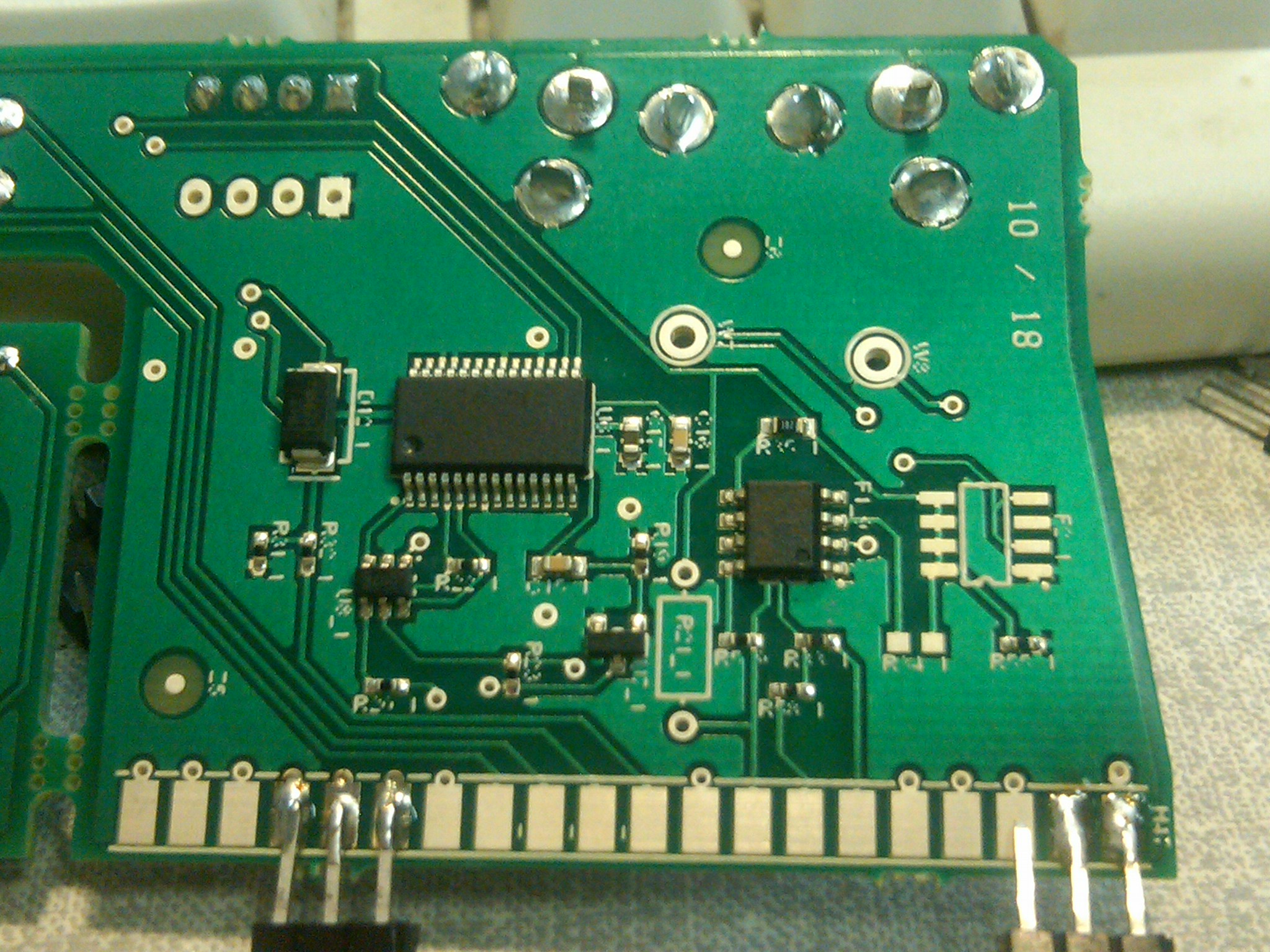
IMG00019-20100525-1644 -- a photo of the board itself. There's not a whole lot that can be figured from that.
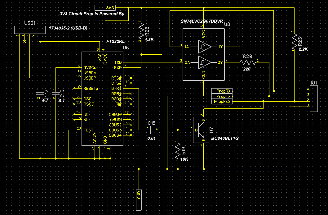
FTDI-schematic -- the schematic I used. Note that it is only the FTDI circuit; note the addition of the SN74LVC2G07DBVR component to prevent the propeller being reset while the USB is unplugged -- this was suggested in an old post, I will try to find it.
▔▔▔▔▔▔▔▔▔▔▔▔▔▔▔▔▔▔▔▔▔▔▔▔
April, 2008: when I discovered the answers to all my micro-computational-botherations!
Some of my objects:
MCP3X0X ADC Driver - Programmable Schmitt inputs, frequency reading, and more!
Simple Propeller-based Database - Making life easier and more readable for all your EEPROM storage needs.
String Manipulation Library - Don't allow strings to be the bane of the Propeller, bend them to your will!
Fast Inter-Propeller Comm - Fast communication between two propellers (1.37MB/s @100MHz)!
The rest of my project works great (the FTDI is on a removable board, along with some other components -- pictured). So i am able to program and test the propeller separate from the FTDI chip. I programmed the propeller to output some information.
As for the problem:
The USB connects to FTDI chip just fine (it installs drivers). But the propeller won't program. The information (previously programed) outputs just fine to PST (through the USB). On the reset pin, the correct reset spike can be seen when I try to program (or detect). The RX line (P31) seems a little fuzzy on the oscilloscope, but the TX pin (P30) appears to reply with data (if I apply a pull-up resistor on the line -- if not is stays at 0V). But still "no propeller chip found".
When I try to bypass the FTDI using the IO1 port (on right of schematic) the RX pin (P31) seems to try to send data, but it never goes above 1/2 Vdd, thus nothing is actually sent, and a pull-up resistor does nothing to help that. The highest it goes is about 1/3 Vdd.
Any ideas?
Information about the attachments:
IMG00019-20100525-1644 -- a photo of the board itself. There's not a whole lot that can be figured from that.
FTDI-schematic -- the schematic I used. Note that it is only the FTDI circuit; note the addition of the SN74LVC2G07DBVR component to prevent the propeller being reset while the USB is unplugged -- this was suggested in an old post, I will try to find it.
▔▔▔▔▔▔▔▔▔▔▔▔▔▔▔▔▔▔▔▔▔▔▔▔
April, 2008: when I discovered the answers to all my micro-computational-botherations!
Some of my objects:
MCP3X0X ADC Driver - Programmable Schmitt inputs, frequency reading, and more!
Simple Propeller-based Database - Making life easier and more readable for all your EEPROM storage needs.
String Manipulation Library - Don't allow strings to be the bane of the Propeller, bend them to your will!
Fast Inter-Propeller Comm - Fast communication between two propellers (1.37MB/s @100MHz)!
2048 x 1536 - 749K
1058 x 692 - 410K
Comments
From the Propeller manual...
"Reset (active low). When low, resets the Propeller chip: all cogs disabled and I/O pins floating. Propeller restarts 50 ms after RESn transitions from low to high."
▔▔▔▔▔▔▔▔▔▔▔▔▔▔▔▔▔▔▔▔▔▔▔▔
My Prop Info&Apps: ·http://www.rayslogic.com/propeller/propeller.htm
My Prop Products:· http://www.rayslogic.com/Propeller/Products/Products.htm
-Phil
Post Edited (Phil Pilgrim (PhiPi)) : 5/26/2010 5:21:01 PM GMT
-Phil
Attached is my "Version 2" of the FTDI circuit. Is that better? I have fixed the current circuit board by placing a pull up resistor on the PropRX line. I based my original thing on the attached (white) schematic, which does not show such a resistor. I had actually almost put one, but decided whoever made the white schematic knew better than I.
@Todd Chapman - yes, the whole thing is kind of confusing, that's why I was mentioning the pin number as well, but I guess since I say "PropRX"/"PropTX" it would make more sense if I were talking about the transmitting and receiving as the Prop sees it, so I have changed it just for you! The wiring was all correct, just the labeling was obfuscated.
▔▔▔▔▔▔▔▔▔▔▔▔▔▔▔▔▔▔▔▔▔▔▔▔
April, 2008: when I discovered the answers to all my micro-computational-botherations!
Some of my objects:
MCP3X0X ADC Driver - Programmable Schmitt inputs, frequency reading, and more!
Simple Propeller-based Database - Making life easier and more readable for all your EEPROM storage needs.
String Manipulation Library - Don't allow strings to be the bane of the Propeller, bend them to your will!
Fast Inter-Propeller Comm - Fast communication between two propellers (1.37MB/s @100MHz)!
Your new schematic looks better. BTW, the reason my Buffered Prop Plug schematic does not show the pullup on the Prop side is that it has to be on the host board, not the Prop Plug. (The Prop Plug itself does not have access to the Prop's Vdd.)
Also, don't count too much on the +5V from the PC being a full five volts. It could be as low as 4.3V, and that's before the drop though your Schottky diode. Strictly speaking, you should include a soft-start circuit to power any additional external circuitry from the USB port, although many people seem to get by without one.
-Phil
I assume you have already ruled out the FTDI driver version.
Post Edited (Todd Chapman) : 5/26/2010 7:23:00 PM GMT
-Phil
Post Edited (Todd Chapman) : 5/27/2010 3:13:30 AM GMT
From the datasheet:
'Sorry if I sounded dismissive; I didn't mean to. I netted your unintentional red herring on the fly while busy with something else, and my main concern was to unhook, filet and flash-freeze it before it flopped into the OP's lap, thus adding to his anxiety.
-Phil
I think the schottky may be enough. It is not my main source of power, it is an in-case-the-power-is-out supply. The schottky is only a 270mV (@30mA) forward drop, so worst case about 4V would be supplied to the LDO regulator I have. What are the chances that after the regulator at least 2.6V isn't being supplied (I won't run the device off of it, I just need to program the device with it)? A soft-start would save me all of 150mV or 200mV (but still may be worth it for more consistent programability)?
▔▔▔▔▔▔▔▔▔▔▔▔▔▔▔▔▔▔▔▔▔▔▔▔
April, 2008: when I discovered the answers to all my micro-computational-botherations!
Some of my objects:
MCP3X0X ADC Driver - Programmable Schmitt inputs, frequency reading, and more!
Simple Propeller-based Database - Making life easier and more readable for all your EEPROM storage needs.
String Manipulation Library - Don't allow strings to be the bane of the Propeller, bend them to your will!
Fast Inter-Propeller Comm - Fast communication between two propellers (1.37MB/s @100MHz)!
Post Edited (Bobb Fwed) : 5/27/2010 8:00:10 PM GMT
Take a look at the soft start circuit I used on the MoBoStamp-pe (#28300). The schematic is at the end of the PDF. BTW, the soft-start circuit recommended by FTDI is totally worthless. Here's a forum discussion on the topic:
http://forums.parallax.com/showthread.php?p=699564
-Phil
Seems like a lot of circuitry for a simple function. Wouldn't there be a simple transistor method for doing a similar thing (with a cap and a couple resistors)? --That is, to slow the sudden hunger of my 3.3V circuit, not to regulate it.
▔▔▔▔▔▔▔▔▔▔▔▔▔▔▔▔▔▔▔▔▔▔▔▔
April, 2008: when I discovered the answers to all my micro-computational-botherations!
Some of my objects:
MCP3X0X ADC Driver - Programmable Schmitt inputs, frequency reading, and more!
Simple Propeller-based Database - Making life easier and more readable for all your EEPROM storage needs.
String Manipulation Library - Don't allow strings to be the bane of the Propeller, bend them to your will!
Fast Inter-Propeller Comm - Fast communication between two propellers (1.37MB/s @100MHz)!
Post Edited (Bobb Fwed) : 5/27/2010 9:57:16 PM GMT
-Phil
I still need the schottky because at some point (most of the time) the 5-ishVOut will be supplied with 12V to 13V. But at least this will save the ?USB? when my 3.3V capacitors get turned loose.
▔▔▔▔▔▔▔▔▔▔▔▔▔▔▔▔▔▔▔▔▔▔▔▔
April, 2008: when I discovered the answers to all my micro-computational-botherations!
Some of my objects:
MCP3X0X ADC Driver - Programmable Schmitt inputs, frequency reading, and more!
Simple Propeller-based Database - Making life easier and more readable for all your EEPROM storage needs.
String Manipulation Library - Don't allow strings to be the bane of the Propeller, bend them to your will!
Fast Inter-Propeller Comm - Fast communication between two propellers (1.37MB/s @100MHz)!
-Phil
The problem with trying to breadboard this stuff is that the FTDI chip is SMD-only component.
Edit: image with component values.
▔▔▔▔▔▔▔▔▔▔▔▔▔▔▔▔▔▔▔▔▔▔▔▔
April, 2008: when I discovered the answers to all my micro-computational-botherations!
Some of my objects:
MCP3X0X ADC Driver - Programmable Schmitt inputs, frequency reading, and more!
Simple Propeller-based Database - Making life easier and more readable for all your EEPROM storage needs.
String Manipulation Library - Don't allow strings to be the bane of the Propeller, bend them to your will!
Fast Inter-Propeller Comm - Fast communication between two propellers (1.37MB/s @100MHz)!
Post Edited (Bobb Fwed) : 6/2/2010 10:27:28 PM GMT
For testing purposes how about the Sparkfun FTDI break-out-board?
www.sparkfun.com/commerce/product_info.php?products_id=718
-Jack
My recommendation would be to copy the softstart circuit used on the MoBo that takes advantage of a Microchip supervisor chip to overcome the FT232R's startup glitches. It's virtually bombproof in that a dead short on the downstream side will not cause the FT232R to reset. It will just reset the supervisor and begin the softstart process over again. (You need to include the 75 ohm resistor and electrolytic cap on the FT's supply to provide some additional filtering and holdup time.) The only downside I've come across is a limitation on how much capacitance it can charge. It won't handle a 1000uF electrolytic, for example, without continuously resetting itself.
-Phil
Post Edited (Todd Chapman) : 5/28/2010 5:09:55 PM GMT
▔▔▔▔▔▔▔▔▔▔▔▔▔▔▔▔▔▔▔▔▔▔▔▔
April, 2008: when I discovered the answers to all my micro-computational-botherations!
Some of my objects:
MCP3X0X ADC Driver - Programmable Schmitt inputs, frequency reading, and more!
Simple Propeller-based Database - Making life easier and more readable for all your EEPROM storage needs.
String Manipulation Library - Don't allow strings to be the bane of the Propeller, bend them to your will!
Fast Inter-Propeller Comm - Fast communication between two propellers (1.37MB/s @100MHz)!
This is from a footnote in the FT232R data sheet
When used in Input Mode, the input pins are pulled to VCCIO via internal 200k
resistors. These pins can be programmed to gently pull low during USB suspend
(PWREN# = “1”[noparse];)[/noparse] by setting an option in the internal EEPROM.
regards,
desiko
▔▔▔▔▔▔▔▔▔▔▔▔▔▔▔▔▔▔▔▔▔▔▔▔
April, 2008: when I discovered the answers to all my micro-computational-botherations!
Some of my objects:
MCP3X0X ADC Driver - Programmable Schmitt inputs, frequency reading, and more!
Simple Propeller-based Database - Making life easier and more readable for all your EEPROM storage needs.
String Manipulation Library - Don't allow strings to be the bane of the Propeller, bend them to your will!
Fast Inter-Propeller Comm - Fast communication between two propellers (1.37MB/s @100MHz)!
I am interested in this question also so I contacted FTDI.
This is the response from an applications Engineer:
"They act as open collector until the configuration has been read, then they drive totem pole."
desiko