

First propeller PCB doesn't work
 flo
Posts: 38
flo
Posts: 38
Hey guys,
Today I received my first custom prop PCB but unfortunately my mac doesn't see it appear in the device list like my PropStick does. I followed the PropStick schematic and a guy at work taught me to solder everything. I double checked all the solder joints and quadruple checked my schematic but didn't see anything wrong... then again I'm a n00b at electronics I'm just glad nothing blew up!
You guys have any suggestions for future layouts or even see the mistake
Today I received my first custom prop PCB but unfortunately my mac doesn't see it appear in the device list like my PropStick does. I followed the PropStick schematic and a guy at work taught me to solder everything. I double checked all the solder joints and quadruple checked my schematic but didn't see anything wrong... then again I'm a n00b at electronics
I'm just glad nothing blew up!You guys have any suggestions for future layouts or even see the mistake
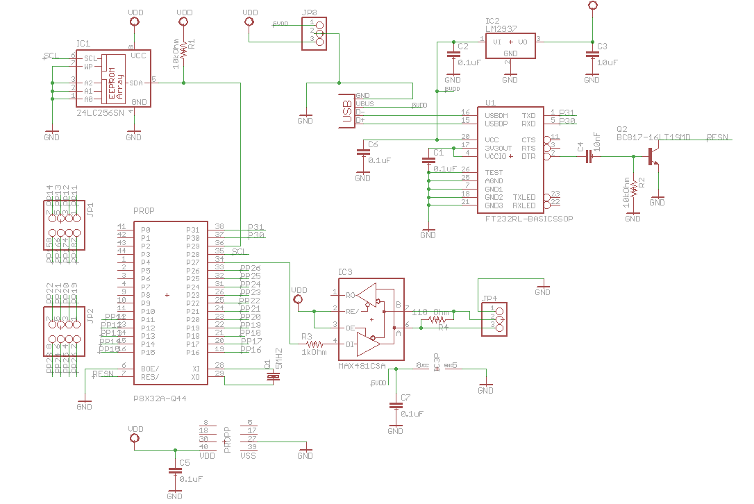
1086 x 726 - 51K
Comments
I'm surprised you learned soldering with a Q44 chip: I'm still trying to get the courage to learn surface mount soldering.
- Looks like a USB Powered device with a jumper to input power, be careful using both.
Post Edited (Zap-o) : 5/22/2010 4:51:53 AM GMT
I would start with a meter to make sure you get power and GND everywhere that it needs to go. A good practice on a the Prop would be to have a .1 cap near each of the 4 power pins to GND.
Anyway, even if the schematic was 100% correct and the PCB was connected the same as the schematic it still doesn't mean that it will work. Better to post the pcb layout and photos too as sometimes the schematic and pcb are correct but assembly isn't.
Just to reiterate what has already been said by others but with a little more emphasis, ALWAYS connect up ALL the VDDs and VSS pins on the Prop or any other chip for that matter as it matters.
▔▔▔▔▔▔▔▔▔▔▔▔▔▔▔▔▔▔▔▔▔▔▔▔
*Peter*
flo, as many have said, post the PCB layout and possibly a high-resolution image of the PCB.
▔▔▔▔▔▔▔▔▔▔▔▔▔▔▔▔▔▔▔▔▔▔▔▔
A woman is the only thing I am afraid of that I know will not hurt me. - Abraham Lincoln
Do you mean QFP, the one with legs? I think that's what he was talking about. The QFN without legs are a little bit trickier as you really want to have pads that extend out a bit more than the ones recommended so that you can easily check and touch up each contact.
So Phil, a skillet hey? Do you save time if it's early in the morning and fry your eggs at the same time? Or maybe if you are British it would be more like fish n chips!
▔▔▔▔▔▔▔▔▔▔▔▔▔▔▔▔▔▔▔▔▔▔▔▔
*Peter*
▔▔▔▔▔▔▔▔▔▔▔▔▔▔▔▔▔▔▔▔▔▔▔▔
Leon Heller
Amateur radio callsign: G1HSM
Post Edited (Leon) : 5/22/2010 7:06:10 AM GMT
English breakfast kippers are deep-fried? Certainly many Propeller chips are routinely deep-fried
▔▔▔▔▔▔▔▔▔▔▔▔▔▔▔▔▔▔▔▔▔▔▔▔
*Peter*
▔▔▔▔▔▔▔▔▔▔▔▔▔▔▔▔▔▔▔▔▔▔▔▔
Leon Heller
Amateur radio callsign: G1HSM
▔▔▔▔▔▔▔▔▔▔▔▔▔▔▔▔▔▔▔▔▔▔▔▔
For me, the past is not over yet.
With a deep-fried Mars bar to follow! It has to be coated in batter, like the fish, of course.
▔▔▔▔▔▔▔▔▔▔▔▔▔▔▔▔▔▔▔▔▔▔▔▔
Leon Heller
Amateur radio callsign: G1HSM
I just know they would come back and be terribly wrong :-(
I have had some made that other people worked up from a schematic
I drew...they worked fine, but I got no feeling of accomplishment.
▔▔▔▔▔▔▔▔▔▔▔▔▔▔▔▔▔▔▔▔▔▔▔▔
*Peter*
▔▔▔▔▔▔▔▔▔▔▔▔▔▔▔▔▔▔▔▔▔▔▔▔
Leon Heller
Amateur radio callsign: G1HSM
I use National Instruments miltisims / ultiboard and its never steered me wrong. Over at advanced circuits you can have them make up a few boards for under $140 and if you are a student its even less expensive. If you are especially tight on cash or need to make a board real cheap (not for production) they will make it without silkscreen for around 30 bucks.
When I solder small ic's and had too much coffee. I make sure to gob solder all over the legs on the part, then using solder wick I remove what is need.
My most recent mistake? I ordered a board with holes too small for the header pins connecting a GPS - this after taking great care in using the datasheet to set up a footprint with the right·positions for those pins and some other connectors. I was so proud to have gotten everything right...until I tried actually putting the GPS on the board. Oops. Two minutes to revise the footprint, and a few weeks to wait for the new boards to arrive. Lesson learned.
Things I'll do from your input:
- always post board layout ( thanks Philldapill)
- connect all power/ground pins on ICs (thanks Zap-o and Peter)
- Add Cap to all power pins to ground (thanks Tod)
- Insure all connections are actually made in Eagle (thanks Tod! Thankfully this was the case)
- Check board artwork no matter how lazy you were that day (Thanks Pablo1234)
- Fish n chips, kippers, and deep friend Mars bars are the sh**! (hahah thanks for the laugh guys!)
- Manually fix autoroute traces in eagle cause some are silly
- move vias that are too close to unrelated pins that make it harder to solder
I've attached the board artwork and again nothing jumps out at me as being wrong. I went back to the magnifying glass at work to double check all the solders and everything is clean. So, I'll wait for Monday so that my coworker can show me how to solder a jumper wire on the power and gnd pins of the prop. He has unbelievably steady hands.
There is an unrouted trace on the Max chip, maybe you saw that. On eagle, the error check feature is very useful both on the schematic and board side. The board error check gives lots of errors for things being too close, but it will show some obvious things too.
Take a pic of the finished board, that always helps too.
Post Edited (Todd Chapman) : 5/22/2010 6:10:46 PM GMT
1 - Prop only board: all voltages seem normal ok
2 - FT232 only board: maintains USB connection and computer sees it fine
3 - Fully soldered board: resets USB connection periodically and continually every ~3 seconds.
I'm suspecting the DTR pin on the FT232 isn't playing nicely with the BOE and RES pins on the prop. Other people seem to have trouble with this:
http://forums.parallax.com/forums/default.aspx?f=25&m=445025
After some googling, I found this:
I don't understand why the transistor schematic I have now doesn't work and what "ATN" stands for in the quote above. Any ideas?
Post Edited (flo) : 6/1/2010 1:43:53 AM GMT
Try cutting the trace to the input of the regulator from the USB power, let the USB power only the 232rl. Find another voltage source and tie it to the input of the regulator, tie the other voltage source GND to the board GND as well though. See if that helps.
Post Edited (Todd Chapman) : 6/1/2010 1:19:50 AM GMT
I'll try this tomorrow evening. What are the implications if this works or doesn't work?
I guess my advice if anyone runs into this problem is probe the USBBDM and USBDP pins on the FTDI chip. Make sure they're at normal voltages. Mine was at a funky 2.7V and thats how I discovered the cold solder. In my defense I didn't solder it; I was being shown cool solder tricks on small pins :-p
Thanks to everyone. I guess my first PCB does work after all!
Jim