Wiring harness decisons, advice needed.
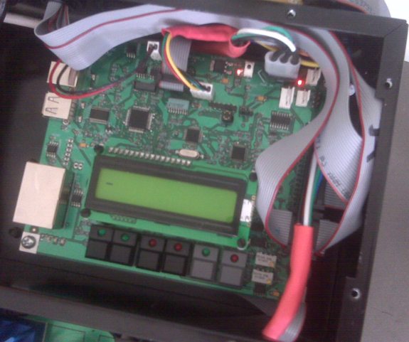
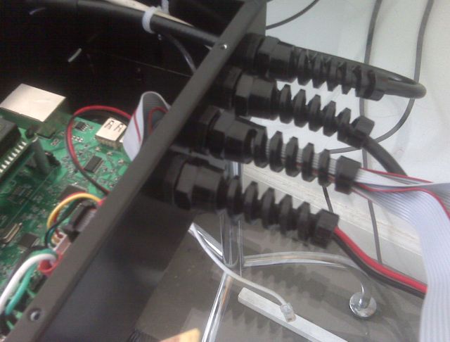
Hey guys, I need some advice on this. I have a product that has a main system controller box, which consists of a main board that is based on the Prop, plus there is a power supply board and motor driver board, with options for other boards to be mounted. The box is already fabriated and I set it up with .85" holes for running cables through strain reliefs as shown. The strain reliefs require that the wire go through it before attaching connectors, which is fine. I like the look and functionality of the reliefs, as they grip the wires of various widths as you tighten it, which is ideal.
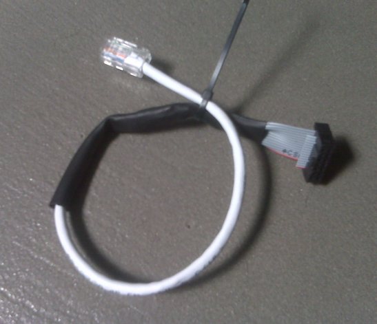
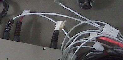
To the issue. The main board has several headers on it, 2x7 and 2x10 on .1" centers, and I use a ribbon cable with easy to attach receptacles that attach in seconds to the ribbon.. The original plan was to just run out ribbon cable to the remote modules that are around 15' to 25' feet away. The problem with this idea is that if the main controller needs to be returned, then the ribbon cables are not detachable outside(near) the box, and cannot be detached at the remote after installation. So this leaves the option of a ribbon>header header>ribbon adapter board that can live outside the main box as a quick release. This is messy. So I came up with the idea to translate the 2x7 header to a single CAT5e cable, and use a CAT5E coupler outside the box which is neat and looks good. However, this means an hour or two of making the conversion cables, as shown in a pic. Of course, I could make a PCB translator. For the next revision I need to have this more thought out. There are 2 each 2x7 headers (14 cond, but only 8 conductors used each). There are 2ea 2x10 headers as well (only 16 conductors required each). So for the 16 conductor requirement, I could use 2 CAT5E cables and couplers, but again this is not as elegant a solution as I would like, and the couplers start adding cost.
The requirements are, the cables must attach inside the box to the PCB by whatever type connector, then go out of the box through the strain relief, then terminate at a connector within a foot of the box for easy disconnect of the system if needed. I am leaning towards putting RJ45 connectors on the board instead of the 2x7 and 2x10, which is not good for real estate , but very quickly and easily get me out of the box to a coupler where someone can simply run CAT5e to the remotes, no mess. Surely somebody down the line will cross up the wires on the ones that need 16 conductors(2 sets of CAT5 per remote), but I can possibly make that fool proof as far as damage control if reversed.
Can anyone think of a better way to do this, such that the user on their end can run the wires to length, cut, and attach connectors as needed? The connectors at the remote side are 2x7 and 2x10 as well, but I can change these out too. I think that crimps for RJ45 are about as techy as I want it to get for the end user.
4 possible remotes, different locations :
2 ea 8 conductors
2 ea 16 conductors
Sorry for the long post.
Post Edited (Todd Chapman) : 5/19/2010 10:55:24 PM GMT


Comments
-Phil
Another option to look at are D-Sub connectors. You can get panel mount D-Sub connectors that terminate to ribbon cable which will make an easy "in box" cable and the outside cable just needs to terminate into the same D-Sub pinout. Either using ribbon cable or other cable if you use a soldercup version. I'll see if I can find a few examples at work and snap some shots. We use tons of D-Subs, ribbon cable, circular connectors (mil spec and commercial), and other connectors that may work for this situation.
Take a look at this too: www.tycoelectronics.com/picturesearch/
▔▔▔▔▔▔▔▔▔▔▔▔▔▔▔▔▔▔▔▔▔▔▔▔
Andrew Williams
WBA Consulting
WBA-TH1M Sensirion SHT11 Module
My Prop projects: Reverse Geo-Cache Box, Custom Metronome, Micro Plunge Logger
Since all I have to do is make a few minor changes on the metal fab design and run a new batch, why not just update the PCB to have RJ 45's on the edge and pop them out of the box on top, instead of using the strain relief? Then just make CAT5 wires and plug them in from the outside straight to the PCB. No internal harnesses at all. It doesn't get simpler than that does it?
I saw this pic on the latest link WBA posted, this gives the idea:
Post Edited (Todd Chapman) : 5/20/2010 6:22:09 AM GMT
What kind of environment will your equipment be in? Dust-free? Dusty? Damp? Wet? Wash-down? Hi-pressure wash-down? Chemical vapor? This may have the greatest bearing on your choice of connectors. Will the cables be subject to abrasion? (I've had cables returned that were nearly unrecognizable, having been run over by forklifts. So it does happen.)
-Phil
www.l-com.com/item.aspx?id=5630&View=Photo
Other useful items found on the same site, chassis mount USB-a/b to 10" leads
www.l-com.com/item.aspx?id=4756
For your app, look at Molex 84702-0005 RJ45 Plug and for a 10' cable look at Molex 84702-1010 RJ45 double ended bayonet cable That will give you full IP67 protection if you desire.
Otherwise, going with a PCB mount is a good idea. The other pictures are of an assembly that we do that uses a small I/O board that mounts to the main board with right angle headers. It is a very slick design and works excellent.
▔▔▔▔▔▔▔▔▔▔▔▔▔▔▔▔▔▔▔▔▔▔▔▔
Andrew Williams
WBA Consulting
WBA-TH1M Sensirion SHT11 Module
My Prop projects: Reverse Geo-Cache Box, Custom Metronome, Micro Plunge Logger
spots on your board?
If you could then this is easy and very cheap.
Just get some very short and cheap ethernet
cables from ebay...they are really cheap if you shop a bit.
Then cut these cables in two and solder the wire ends to
your board and route the cable through a hole or some
other sort of strain relief.
Then buy a bag of those really cheap cat5 couplers from
ebay.
You could make the ends of the cat5 cables available through a
hole or slot in the cabinet and just stick the adapters on the ends.
The end user could use any cat5 cable to hook things up then.
Cat5 extension cables are pretty cheap on ebay also...so you could supply
several at low cost.