

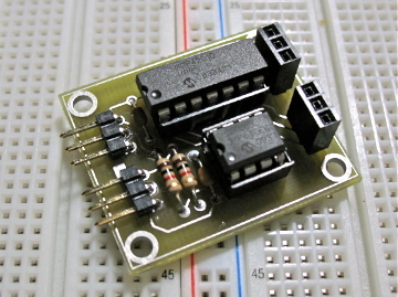
What could you use this for? It's a two channel, RC controlled digital pot.
 W9GFO
Posts: 4,010
W9GFO
Posts: 4,010
I initially made this board just for myself, it is used to replace the joystick on an electric wheelchair controller so that I can roboticize it. It can either be hooked up to an RC receiver or a microcontroller.


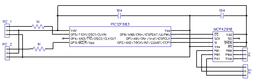
It has two RC inputs and two digital pots. Each digital pot is 10k and has 256 steps. As a safety, if it goes for half a second without receiving a valid pulse it sets the pots to mid scale. So a microcontroller would only need to update the pulse three times a second for solid operation. Although faster would be better for smooth control.
I'm wondering if I should make some boards and put this on GadgetGangster. Can you think of any uses for it?
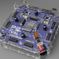
360 x 269 - 63K
867 x 289 - 7K
Comments
▔▔▔▔▔▔▔▔▔▔▔▔▔▔▔▔▔▔▔▔▔▔▔▔
·Now wanting to learn Spin· Thanks for any·
·
·
·
·
Sam
Also, R/C light dimmers, remote display of an analog signal on a metter, adjustable zapping voltage for a dog collar (see the Marathon thread).
I'm sure guys in the lighting and stage prop (as opposed to Parallax Prop) would have hundreds of uses.
Lost of potential uses, but in some/many cases, the board, as it exists, may not be a "complete" solution.
▔▔▔▔▔▔▔▔▔▔▔▔▔▔▔▔▔▔▔▔▔▔▔▔
John R.
Click here to see my Nomad Build Log
The curent capacity of the pots is quite low, only 1 ma.
The only thing that I can think of where it is a "complete" solution is a replacement pot for electric scooter/wheelchair motor controllers. It could replace the throttle or joystick so that it could be turned into a robot or RC controlled vehicle.
Can you explain how this would be used?
I have two wheelchairs that I would like to use in a couple projects.
Both chairs are Invacare Pronto. I think one is the M51 and one is the M71. Both use the same joystick and controller.
Joystick = MK5 SPJ+
Controller = DK-PMA02 MK 5 NX
They use 4 conductors jacks.
Here are some images (not mine) of the items I have..
Joystick..
Plug..
Controller..
My understanding, if I am correct, is that the circuit you created was designed to plug into the current controllers four wire plug and to bypass the joystick completely, so that I could connect an R/C receiver right to the circuit board?
Rick
Not quite. It is meant to take place of the joystick only - and by that I don't mean the thing with the buttons and lights on it - just the part you steer with. You would need to open up the joystick controller (the thing you have labeled as "joystick" in your first image), remove the joystick and wire the digital pot in it's place.
This is an example of a joystick;
Ok, I understand. I would still need the original joystick controller electronics in order to turn the electric wheelchair on and off.
I have just a couple more questions, if you don't mind...
Does the above circuit board control direction only, or would it proportionally control the speed based on how far the stick is advanced?.
I realize, by the designation letters, that RC1 and RC2 connect via servo wires to the R/C receiver (or a microcontroller), but how would P1 and P2 connect to the joystick controller board.
I really appreciate your time in answering my questions.
Rick
The middle pin of the pot connector is connected to the wiper and the other pins are connected to the ends of the pot ... there's a fixed 10K resistance between the end pins and the center pin is connected to an electronic "wiper" somewhere between the two end connections.
Ok, got it. Thanks
Rick
73's
KF5TOQ
Randy Barbee
I programmed the PICs using PIC Basic Pro. It is very similar to PBasic, which is what the Basic Stamp uses.
Yes, but way overkill for this application. All you are doing is reading PWM then outputting a serial string to the digital pot. But if you want to learn to program the Propeller this could be a good starting point, and you may find other interesting applications for it.
I think this is exactly what I'm looking for. I've been searching for "RC controlled pot" and coming up empty.
I want to remotely control the throttle signal 0 - 5V going into my motorized cupcake's motor controller. Your RC Pot would do the trick I think.
Do you have any on hand you'd be willing to part with?
I was wondering if you have any of the circuit boards you would be willing to part with?