

Anyone interested in co-building a robotic arm?

I'm interesting in building a robotic arm similar to those found at lynxmotion. But controlled by a propeller or basic stamp. I feel that I could build the mechanics of the arm pretty well but I would definitely need help with the software to run it, and the circuits for the motors.
I have a CNC router and can produce the parts, although my CNC is a Hobby CNC, so I can only cut plastic and soft metal. I'm Fluent in CAD and Sketchup. and can take a design from paper to actual part very easily.
I would like to build a robotic arm out of Sintra (expanded PVC) or HDPE. This would keep the cost and weight to a minimum and also make it easy to machine.
I have about 25 Identical stepper motors that I can use for this project. and I have a limited but cheap source of Sinatra, and HDPE.
I'm suggesting that we all input our thoughts on the best design, make a prototype, and then once we feel we are at a usable level, make identical robotic arms for everyone in the group.
I would like to keep the entire project under $50.00 which I think is very doable, if we use the motors that I have.
I'd like to keep the number in the group to about 5 give or take. I want the project to be open source and plan to publish the project to the forum once completed.
let me know if your interested.
▔▔▔▔▔▔▔▔▔▔▔▔▔▔▔▔▔▔▔▔▔▔▔▔
DGSwaner
"When in doubt, use C4" - Jamie Hyneman, Myth Buster
Post Edited (Dgswaner) : 5/11/2010 4:04:54 AM GMT
2048 x 1536 - 1M
1536 x 2048 - 1M
Comments
AFA materials, HDPE is cheap, but you can't glue to it. ABS, HIS, & PVC glue well. I wonder if plastic plumbing pipes (ABS or PVC) would be good for your design. Home Depot cheap, and easy to source. People build some amazing things out of PVC pipe and all the various joints.
▔▔▔▔▔▔▔▔▔▔▔▔▔▔▔▔▔▔▔▔▔▔▔▔
·"If you build it, they will come."
What type of stepper motors are you using? I can design a great board for the controller and have it connected to the BS series of Stamps. The BS2px is my favorite of the 2 series, I'm still learning Spin but at slow motion rate so I don't miss anything and have to re-read it again.
Just let me know if you want me in on this project.
Jax
▔▔▔▔▔▔▔▔▔▔▔▔▔▔▔▔▔▔▔▔▔▔▔▔
If a robot has a screw then it must be romoved and hacked into..
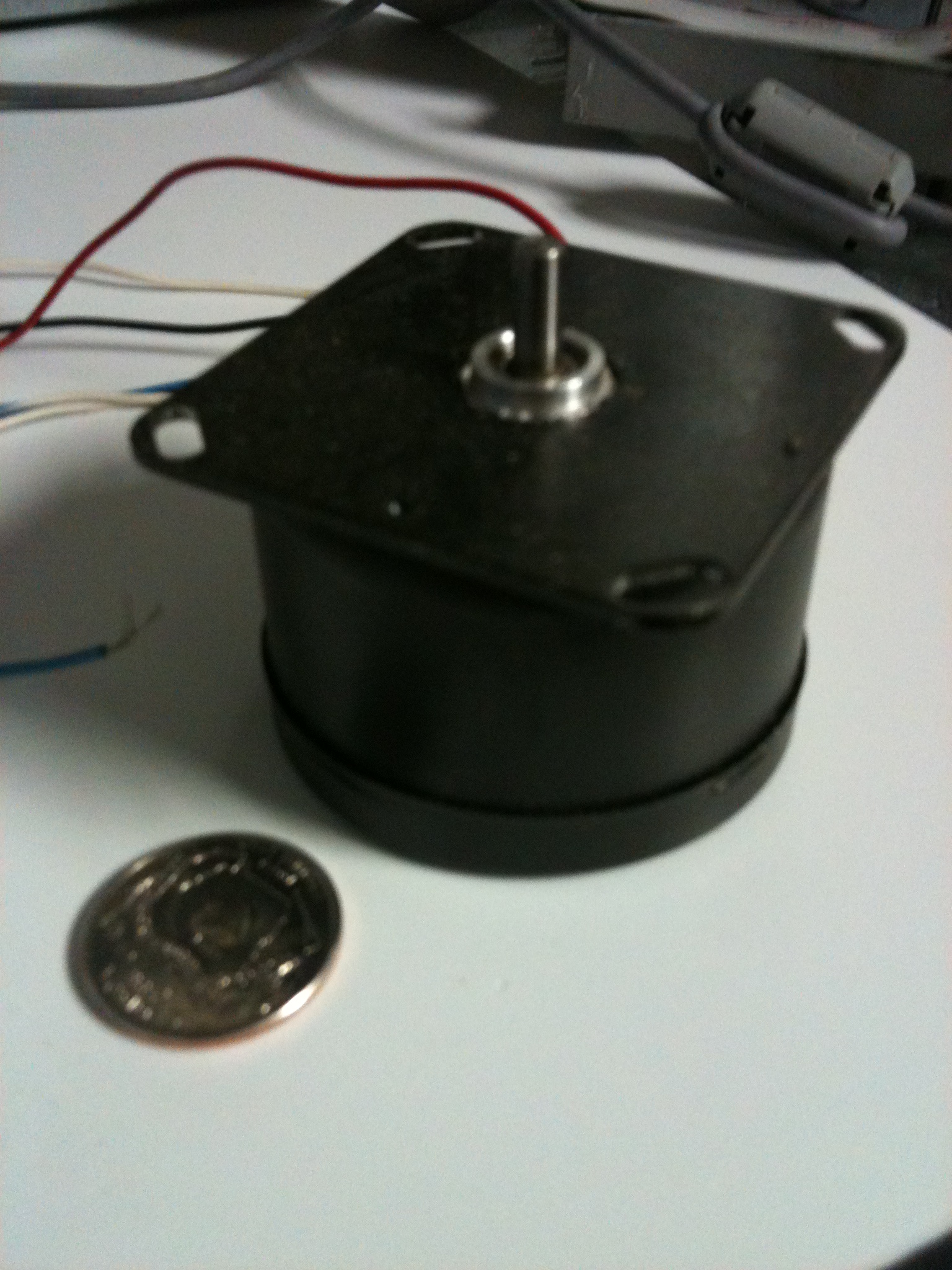
@GWJAx your in! the steppers I have are Hurst steppers, I'll post a picture of them asap.
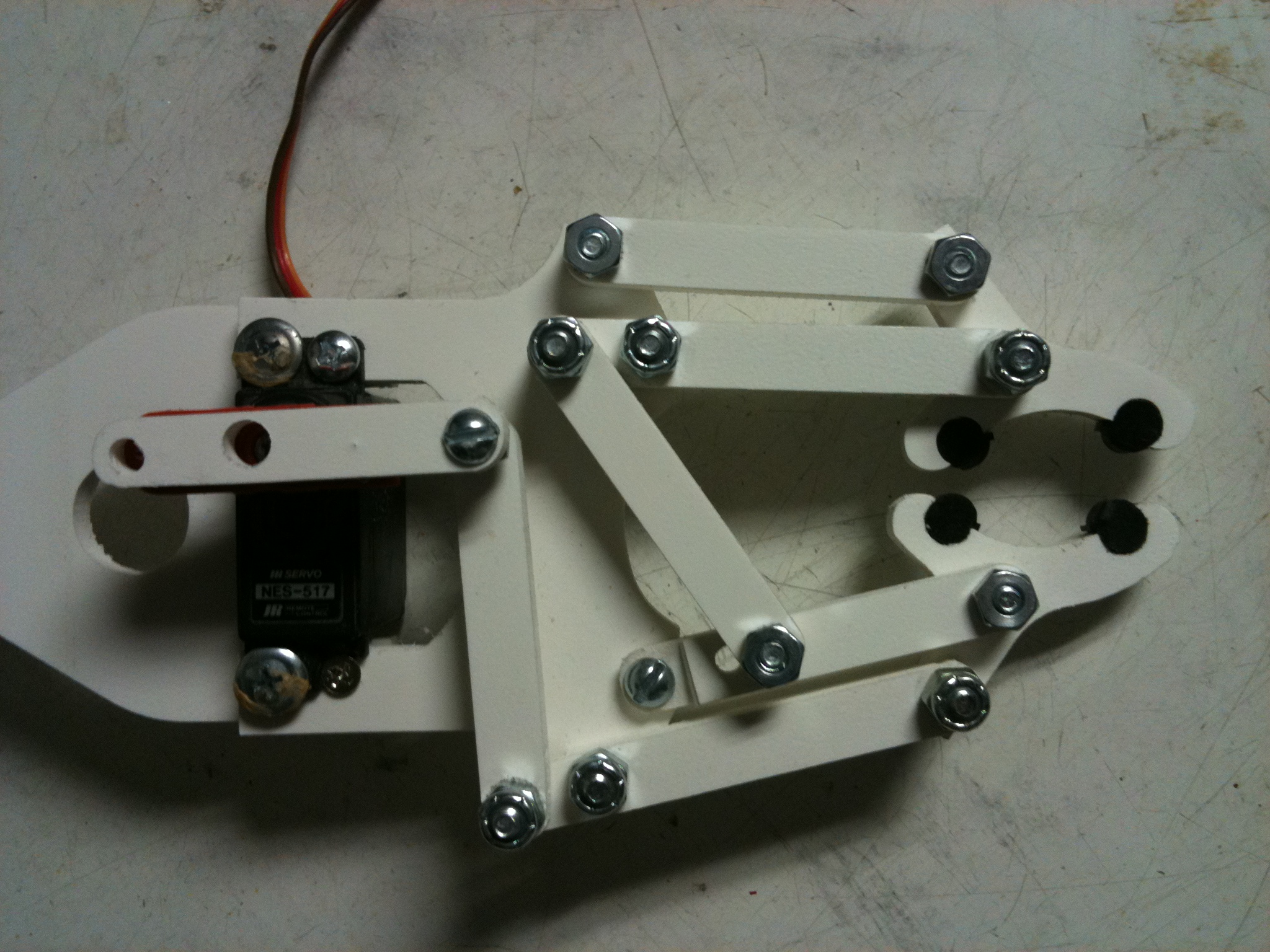
oops addes them to the wrong MSG, the gripper was cut out of 1/4" Sintra. the other is of course the motor, Hurst Prinston, Ind. RPM Model PAS. 5V DC 8.5 W. P/N sp-2109
and have 6 wires. I honestly have no idea if these are good for this application. but it's what I have.
▔▔▔▔▔▔▔▔▔▔▔▔▔▔▔▔▔▔▔▔▔▔▔▔
DGSwaner
"When in doubt, use C4" - Jamie Hyneman, Myth Buster
Post Edited (Dgswaner) : 5/11/2010 4:10:09 AM GMT
Personally, I would start at the claw/gripper and work backwards, since the forces, torques, and motor size/weight are smallest there. Then increase the motor sizes and gear ratios proportionally as you work backwards to the shoulder pivot.
▔▔▔▔▔▔▔▔▔▔▔▔▔▔▔▔▔▔▔▔▔▔▔▔
·"If you build it, they will come."
with out a gear box installed which yours do not have, the motor can withstand 200 oz/in
I agree with erco about starting with the gripper and working backwards due the the forces etc...
Jax
▔▔▔▔▔▔▔▔▔▔▔▔▔▔▔▔▔▔▔▔▔▔▔▔
If a robot has a screw then it must be romoved and hacked into..
A magazine article 20 years ago showed how someone "computer controlled" an Armatron by moving the existing mechanical joysticks with multiple servos. Talk about going the long way around!
The OWI Edge robot arm is a beautiful kit, but I think it would be hard to modify for servos or feedback pots.
IMHO, probably the best way to quickly get an arm working is simply to use a bunch of servos connected together. One servo per joint, connected to the next via a stiff link. Again, start with a lightweight servo for the gripper and using progressively larger servos as you work backwards. Different servos use different gear ratios; I think higher reduction servos would be best for strength, repeatability, durability, and holding a specified position without sending pulses constantly.
▔▔▔▔▔▔▔▔▔▔▔▔▔▔▔▔▔▔▔▔▔▔▔▔
·"If you build it, they will come."
GW, That looks like the exact motors. pricey little suckers! I forget what I paid for them but it wasn't anywhere near that price.
I agree with you on the top down design, I have already been looking into gripper designs, the one I posted functions pretty well, but needs to be tweaked a little.
what are we thinking as far as over all design, I basically want to build a enlarged version of the Armatron. but not part by part.
what are we looking for as far as over all specs? reach, strength, speed?
is there a site or tool we can use to better communicate?
▔▔▔▔▔▔▔▔▔▔▔▔▔▔▔▔▔▔▔▔▔▔▔▔
DGSwaner
"When in doubt, use C4" - Jamie Hyneman, Myth Buster
Don't laugh: aluminum cans from Red Bull drinks... so the arm may look a bit like the OWI trainer:
▔▔▔▔▔▔▔▔▔▔▔▔▔▔▔▔▔▔▔▔▔▔▔▔
·"If you build it, they will come."
I'm working on an arm, too, but it's way below your level, so I just want follow the development posts and try to learn something.....
Gramps
▔▔▔▔▔▔▔▔▔▔▔▔▔▔▔▔▔▔▔▔▔▔▔▔
'What is your life?"
saint James 61 A.D.
Between Sintra and HDPE? I THINK I'd use Sintra just because it's slightly more rigid and you'd probably have a better chance with adhesives. Any chance you could use ABS instead? It visually about the same as Sintra, but MUCH more rigid and about the same price....... as long as you're talking 1/4" material. If you are planning to use 1/2" thick or thereabout, I'd probably use HDPE. All these materials won't take a thread very well.... not really. The best thing is adhesive or a wood screw...... yea, I'm an expert on my opinions [noparse]:)[/noparse]
If it helps any, I built a robot arm out of 1/4" blue core foam for a prototype / work out the design. Before you laugh, it was amazingly strong. It'd lift up to about 8oz. I tried to upload the video (taken with my cellphone) but it was some weird QT format and the Forums wouldn't take it.
▔▔▔▔▔▔▔▔▔▔▔▔▔▔▔▔▔▔▔▔▔▔▔▔
"puff"...... Smile, there went another one.
@Gramps I think you are giving me, at least, way too much credit.
@spiral if you want in we could use the help. I prefer sketchup for design, but I can't go from sketchup to CNC very well. sketchup can't export arch's or poly lines very well. so perhaps when we get closer, If you could do a model in SW to verify we have everything in order. getting DXF would save a lot of time in the CAM process.
I have Friday off and plan to do a test on my concept and will hopefully be able to do a first draft model in sketchup.
@Mike G if I was smart enough to respond to your post I would.... I get the work area. the rest went over my head.
▔▔▔▔▔▔▔▔▔▔▔▔▔▔▔▔▔▔▔▔▔▔▔▔
DGSwaner
"When in doubt, use C4" - Jamie Hyneman, Myth Buster
I included an image of my robot arm model. The base is 3/4" MDF with a 4" lazy susan (thrust) bearing for the rotating base. There's a servo and coupling underneath as well as two bearings to handle side loads. I pivot the shoulder joint in the mid-section so I can counterweight the far end with lead. It lets me use the small standard sized RC servos I had.
Everything rides on bearings, so the servos only see rotational loads. The actual arm is 1/4" blue core foam with a magnet for a hand because I didn't have a gripper.
It's FYI. You don't have to use my design although I THINK it would scale well. You'd just use more lead.
▔▔▔▔▔▔▔▔▔▔▔▔▔▔▔▔▔▔▔▔▔▔▔▔
"puff"...... Smile, there went another one.
The steppers might have a good chance of directly driving the arm at the pivot points like I did. It's simple and cheap, but what I noticed was the arm will bounce when stopping abruptly or when it travels over the center of gravity. The threaded rod drive probably wouldn't have that problem. Timing pulleys and belts would be an excellent drive system, although expensive from the parts I've seen.
▔▔▔▔▔▔▔▔▔▔▔▔▔▔▔▔▔▔▔▔▔▔▔▔
"puff"...... Smile, there went another one.
Gramps has got me intrigued with the idea of designing the controls for his arm.
I'm picturing a coat sleeve with attached glove you could slip your arm into. (A strap across the chest to hold it in place)
I'm actually thinking that a couple of accelerometers might be able to be used?
(Think: Gramps shadowbot x10 [noparse]:)[/noparse]
OBC
▔▔▔▔▔▔▔▔▔▔▔▔▔▔▔▔▔▔▔▔▔▔▔▔
Are you Propeller Powered? PropellerPowered.com
Visit the: PROPELLERPOWERED SIG forum kindly hosted by Savage Circuits.
Bean
▔▔▔▔▔▔▔▔▔▔▔▔▔▔▔▔▔▔▔▔▔▔▔▔
- - - - - - - - - - - - - - - - - - - - - - - - - - - - - - -
Use BASIC on the Propeller with the speed of assembly language.
PropBASIC thread http://forums.parallax.com/showthread.php?p=867134
March 2010 Nuts and Volts article·http://www.parallax.com/Portals/0/Downloads/docs/cols/nv/prop/col/nvp5.pdf
- - - - - - - - - - - - - - - - - - - - - - - - - - - - - - -
There are two rules in life:
· 1) Never divulge all information
- - - - - - - - - - - - - - - - - - - - - - - - - - - - - - -
If you choose not to decide, you still have made a choice. [noparse][[/noparse]RUSH - Freewill]
▔▔▔▔▔▔▔▔▔▔▔▔▔▔▔▔▔▔▔▔▔▔▔▔
'What is your life?"
Saint James 61 A.D.
FWIW: Threaded rod=Leadscrew.
▔▔▔▔▔▔▔▔▔▔▔▔▔▔▔▔▔▔▔▔▔▔▔▔
·"If you build it, they will come."
I would like to get in on your project building a robotic arm similar to those found at lynxmotion.
I had been looking at “The Big Gripper” at www.budgetrobotics.com/shop/?cat=159 the kit with a servo is $26.95 just for the gripper. A set of the fingers is just $2.95. The problem is it just the gripper not a whole arm and has no electronics other than the servo.
I just took a look at the lynxmotion arms they look great and hope your project turns out great too.
I don’t have much experience with the mechanics or software, but I do with wiring and electronics.
Please let me if I can get in on this project.
Regards,
zappman
▔▔▔▔▔▔▔▔▔▔▔▔▔▔▔▔▔▔▔▔▔▔▔▔
Visit Zappman's Blog at Savage Circuits
Post Edited (zappman) : 5/16/2010 10:20:04 PM GMT
Gramps
▔▔▔▔▔▔▔▔▔▔▔▔▔▔▔▔▔▔▔▔▔▔▔▔
'What is your life?"
Saint James 61 A.D.
Hi Gramps,
The best picture I can find is on page 8 of the manual located at www.budgetrobotics.com/manuals/biggripper/biggripper.pdf, the fingers are shown in black.
If i bought this gripper, instead of putting tubing on the fingers to cushion them as recommended in the manual , I was going to dip them in "tool grip" "plastic dip" www.amazon.com/Plastic-Dip-Intl-11602-6-Plasti-Dip/dp/B000ZN1T16/ref=pd_bxgy_hi_img_c
Regards,
zappman
you'll have to use a little imagination, but the concept should be easy to see once you know whats going on.
The Right Picture:
Imagine in place of my hand, there is a connector with a joint holding the angled rod this connector will ride the threaded rod back and forth.
the other end of the angled piece is connect to another part of the arm, much like the piece on the bottom. as the angled rod slides back and forth it opens and closes the joint.
middle Picture:
This part of the arm is mostly finished, the rods will be cut to length, the two outer bars will be smooth rods, and only the middle will be threaded. a stepper will be connected to the middle rod. and the "connector" will move back and forth on the 3 rods. driven by the threaded rod. as the connector gets closer to the joint, the angled push rod, opens the joint and pushes the other part of the arm straight.
The next part of the arm will be just about like the one here and shown as only one side.
▔▔▔▔▔▔▔▔▔▔▔▔▔▔▔▔▔▔▔▔▔▔▔▔
DGSwaner
"When in doubt, use C4" - Jamie Hyneman, Myth Buster
Post Edited (Dgswaner) : 5/17/2010 5:59:13 AM GMT
Jim