

Strange Circuit Failure
 Adam S
Posts: 10
Adam S
Posts: 10
Hi all,
I'm pretty inexperienced when it comes to electronics and the like, but I'm trying to make a device that senses the temperature and records it to the EEPROM onboard the BS2.
I know EEPROM has a limited lifetime, but I don't plan on anywhere near 1,000,000 writes.
I'm using the DS1620 temperature chip and the Board of Education. The Board of Education is connected to the Boe Bot chassis, but nothing associated with the Boe Bot is connected.
I eventually got everything to work (and work reliably, I tested it alot) and I made a second prototype on another breadboard as well as a soldered version. The other day I went to test my soldered version, and it didn't work. The DS1620 just reads one temperature, even if I cool it off alot.
I then tested my breadboarded version and the version on the Boe Bot, and both of those failed as well. I had one extra DS1620 and I replaced the old one on the Boe Bot with it and then the setup worked like it used to. But when I tried that same DS1620 in the breadboarded version, it didn't work.
I don't know what is going on here. Everything worked, and now all three circuits don't. It's weird that they would all fail at once.
Here are my thoughts on a cause:
1. Static damage to either the DS1620 or the BS2. I don't know how sensitive these parts are. Its not like I went around rubbing them through my hair though.
2. Since all 3 circuits now fail, that seems to point to a failure of the one part shared between them, which is the BS2 (each circuit has a socket that receives the BS2). But at the same time, the BS2 performs the data dump to the debug screen just fine, so if it is a BS2 failure, it is a sneaky one.
Here is the code to read the stored temp data:
Here's temperature recording code. I understand how most of it works, but I am guilty of copying code from here (page 16):
www.parallax.com/Portals/0/Downloads/docs/prod/appkit/ds1620thermometer.pdf
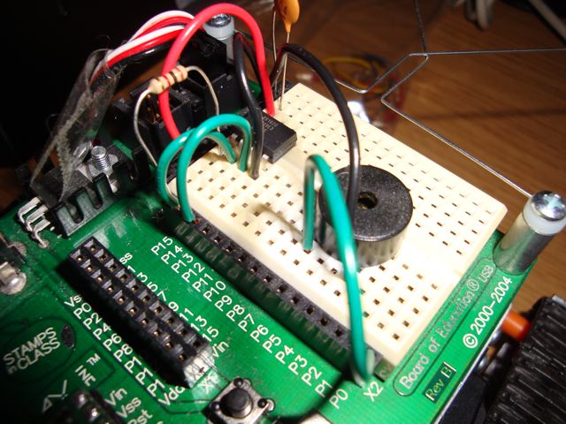
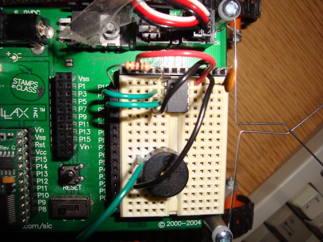
I'm also attaching a picture of the wiring configuration on my Board of Education (the wiring is the same on my other 2 boards). In the pictures it shows the Boe Bot servos connected, but I have disconnected them and it still doesn't work. I'm using a 1k ohm resistor and a .1 micro-farad capacitor, per the instructions I found here (page 12):
www.parallax.com/Portals/0/Downloads/docs/prod/edu/WebApplied%20Sensors%20V2.0.pdf
Any insight is greatly appreciated. Also, let me know if you need more information.
Thanks,
Adam
One more thing I thought of: Some condensation did form when I took the circuit out of the freezer after testing it each time. It evaporated quickly though and the one time the BS2 wasn't recognized, it was recognized after the condensation dried up.
Post Edited (Adam S) : 5/9/2010 5:45:10 PM GMT
I'm pretty inexperienced when it comes to electronics and the like, but I'm trying to make a device that senses the temperature and records it to the EEPROM onboard the BS2.
I know EEPROM has a limited lifetime, but I don't plan on anywhere near 1,000,000 writes.
I'm using the DS1620 temperature chip and the Board of Education. The Board of Education is connected to the Boe Bot chassis, but nothing associated with the Boe Bot is connected.
I eventually got everything to work (and work reliably, I tested it alot) and I made a second prototype on another breadboard as well as a soldered version. The other day I went to test my soldered version, and it didn't work. The DS1620 just reads one temperature, even if I cool it off alot.
I then tested my breadboarded version and the version on the Boe Bot, and both of those failed as well. I had one extra DS1620 and I replaced the old one on the Boe Bot with it and then the setup worked like it used to. But when I tried that same DS1620 in the breadboarded version, it didn't work.
I don't know what is going on here. Everything worked, and now all three circuits don't. It's weird that they would all fail at once.
Here are my thoughts on a cause:
1. Static damage to either the DS1620 or the BS2. I don't know how sensitive these parts are. Its not like I went around rubbing them through my hair though.
2. Since all 3 circuits now fail, that seems to point to a failure of the one part shared between them, which is the BS2 (each circuit has a socket that receives the BS2). But at the same time, the BS2 performs the data dump to the debug screen just fine, so if it is a BS2 failure, it is a sneaky one.
Here is the code to read the stored temp data:
' {$STAMP BS2}
' {$PBASIC 2.5}

'Adam Stevens
'12-21-09
'Code to Read 16-bit data points from BS2 EEPROM and display in the Debug screen.
'Read *location*, {Word} *variable*
         'include WORD if the data to be read is WORD sized, and the low/high bytes will
         'automatically be taken and put into *variable*.

memloc VAR Word        'word, b/c data locations will be > 255 for flight.
storedtemp VAR Word

'signal program start
FREQOUT 0, 2000, 3000

'change to 600 for recovering flight data (300 2-slot locations)
FOR memloc = 0 TO 38 STEP 2          '0 to 40 checks 20 (2-location) spots.

  'Don't play around with lowbyte/highbyte commands, just tell the program it is a WORD when
      'reading the data point and make sure the For-Next loop is STEP 2 because low/high will
      'automatically be taken into account when using WORD qualifier.
  READ memloc, Word storedtemp

  DEBUG SDEC storedtemp, CR

NEXT

'At this point all the user has to do is copy-paste the data from the
     'debug screen.
PAUSE 50000
END
Here's temperature recording code. I understand how most of it works, but I am guilty of copying code from here (page 16):
www.parallax.com/Portals/0/Downloads/docs/prod/appkit/ds1620thermometer.pdf
' {$STAMP BS2}
' {$PBASIC 2.5}

Temp       VAR    Word              ' Word variable to hold 9-bit data.
Sign       VAR    Temp.BIT8       ' Sign bit of raw temperature data.
T_sign     VAR    Bit               ' Saved sign bit for converted temperature.
memloc     VAR    Word              ' the location to store the latest reading.
counter    VAR    Word              ' counter for the main FOR loop

memloc = 0

FREQOUT 0, 2000, 3000

OUTS=%0000000000000000               ' Define the initial state of all pins,
     'FEDCBA9876543210
DIRS=%1111111111111111               ' as low outputs.


'DS1620 has been preprogrammed to setting 3.
'The loop reads the latest temperature from the DS1620 and saves it to EEPROM.

HIGH 13                              ' Select the DS1620.
SHIFTOUT 15, 14, LSBFIRST, [noparse][[/noparse]238]     ' Send the "start conversions" command.
LOW 13                               ' Do the command.

FOR counter = 0 TO 20

  PAUSE 1000

  HIGH 13                            ' Select the DS1620.
  SHIFTOUT 15, 14, LSBFIRST, [noparse][[/noparse]170]   ' Send the "get data" command.
  SHIFTIN 15, 14, LSBPRE, [noparse][[/noparse]Temp]     ' Get the data, assign to DSDATA
  LOW 13                             ' End the command.

  T_sign = Sign                      ' Save the sign bit of the reading.
  Temp = Temp/2                      ' Scale reading to whole degrees C.

  IF T_sign = 0 THEN
    GOTO DisplayData
    GOTO SaveData
  ENDIF

  IF T_sign = 1 THEN
    Temp = Temp | $FF00              ' Extend sign bits for negative temps.
    GOTO DisplayData
    GOTO SaveData
  ENDIF

NEXT


DisplayData:
  DEBUG SDEC Temp," degrees C",CR     ' Show signed temperature in C.
  RETURN

SaveData:
  WRITE memloc,   DSdata.LOWBYTE
  WRITE memloc+1, DSdata.HIGHBYTE
  memloc = memloc + 2
  RETURN
I'm also attaching a picture of the wiring configuration on my Board of Education (the wiring is the same on my other 2 boards). In the pictures it shows the Boe Bot servos connected, but I have disconnected them and it still doesn't work. I'm using a 1k ohm resistor and a .1 micro-farad capacitor, per the instructions I found here (page 12):
www.parallax.com/Portals/0/Downloads/docs/prod/edu/WebApplied%20Sensors%20V2.0.pdf
Any insight is greatly appreciated. Also, let me know if you need more information.
Thanks,
Adam
One more thing I thought of: Some condensation did form when I took the circuit out of the freezer after testing it each time. It evaporated quickly though and the one time the BS2 wasn't recognized, it was recognized after the condensation dried up.
Post Edited (Adam S) : 5/9/2010 5:45:10 PM GMT
640 x 480 - 81K
640 x 480 - 81K
Comments
Of course if you had another BS2 that would be nice to test that in the same environment. Was the BS2 in the socket when the soldering was taking place? You could try to connect the DS1620 on different pins on the BS2 in case some of them got toasted.
Rick
The BS2 wasn't in the socket, although it is possible that I might have overheated the DS1620 when I soldered that. That might explain the soldered circuit, but the breadedboarded circuits used DS1620's that have never seen heat.
The BS2 I am using is Revision G. I have a Revision F that I bought on Ebay a while ago, but when I plugged it into the Board of Education to try it, the computer didn't recognize it. So I'm not sure what the deal is with that.
I'll try using different pins on my Revision G BS2 and post my results.
Thanks,
Adam
Thanks,
Adam
Mike, I'm more than willing to try your suggestion for testing the I/O pins, but I'm afraid I don't know enough about circuits to know what you mean by "you can attach a back-to-back pair of LEDs (and a 330 Ohm series resistor) between two I/O pins". Could someone give me a quick description of these connections?
Thanks,
Adam
a:for b0=1 to 15
toggle b0
next
pause 500
goto a
which continuously drives all the pins high then low, each half second. You can individually check the voltage on each pin with a multimeter, or an LED/resistor to ground.
▔▔▔▔▔▔▔▔▔▔▔▔▔▔▔▔▔▔▔▔▔▔▔▔
·"If you build it, they will come."
I tested each I/O pin by toggling it and checking to see if it flashed an LED/resistor combo. I used this code:
' {$STAMP BS2}
' {$PBASIC 2.5}
a:
    TOGGLE 0      'changed circuit and toggle # from 0-15
    PAUSE 500
GOTO a
and the LED flashed for each I/O pin. That seems to suggest to me that my I/O pins are good, and therefore my entire BS2 is good since the code downloaded in the first place. Are there any other tests I can run? Is there some way I can be certain that my Board of Education isn't damaged somehow?
I'm going to try rebuilding my circuit from the ground up to see if maybe something just needed to be reseated.
I read through what I posted earlier and I suppose I should include a more thorough description of the problem:
When this was working (and it worked reliably for a good 10-15 trials), the DS1620 would send temperature values to the DEBUG screen that changed as I warmed/cooled the thermometer. The temperature values would then be stored into the onboard EEPROM.
Now the same temperature reading is sent to the DEBUG screen (usually around 19-20 degrees C) regardless of what I do to warm/cool the thermometer. I had an extra DS1620 lying around that I popped in to see if that was the problem and it worked once, but then the next time I ran it the new DS1620 started spitting out the same repetitive value as the old DS1620.
I am using the same code to initially configure the DS1620 as I was when the program worked:
' {$STAMP BS2} ' {$PBASIC 2.5} ' Applied Sensors - DS1620Configuration.bs2 ' Configure the DS1620 for CPU one-shot temperature readings and conversion. LOW 13 ' Puts the DS1620 in the waiting state. FREQOUT 0, 1000, 3800 ' Sound shows us the program is running. HIGH 13 ' Tells the DS1620 a command is coming. SHIFTOUT 15, 14, LSBFIRST, [noparse][[/noparse]12,3] ' Command to set DS1620 configuration 3. LOW 13 ' Completes the command cycle. END ' End of program.-Adam
Jim