Shop OBEX P1 Docs P2 Docs Learn Events
Surface mount prop board — Parallax Forums

Surface mount prop board

CenlasoftCenlasoft Posts: 265
edited 2010-05-05 06:24 in Propeller 1
Hello,
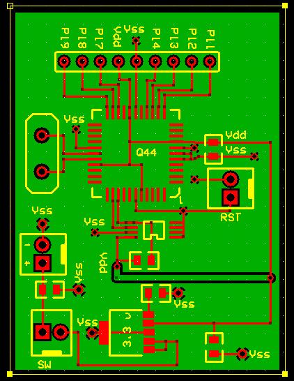
I wanted to try my luck at making my project with smt components. I have attached an image of my prop pcb. Please critique my work. Have I missed anything? Thanks for your comments. The pcb circuit was done in ExpressPcb.
Curtis
422 x 546 - 53K

Comments

  • LeonLeon Posts: 7,620
    edited 2010-05-04 16:26
    Schematic?

    ▔▔▔▔▔▔▔▔▔▔▔▔▔▔▔▔▔▔▔▔▔▔▔▔
    Leon Heller
    Amateur radio callsign: G1HSM
  • BigFootBigFoot Posts: 259
    edited 2010-05-04 16:29
    I would make the 5V & 3.3V traces wider, you have a good ground plane.
    I would also add a couple of tantalum capacitors (10 to 47uF), one on
    each side of the voltage regulator.

    Russ
  • Martin HodgeMartin Hodge Posts: 1,246
    edited 2010-05-04 16:29
    You can probably eliminate the large isolated trace on the back layer -- and eliminate two vias -- by running that trace on the upper layer directly from pad 4 (2?) of the vreg to the left pad of the resistor.
  • RaymanRayman Posts: 14,887
    edited 2010-05-04 16:58
    Something looks wrong with your "RST" header... Aren't both pins grounded?

    ▔▔▔▔▔▔▔▔▔▔▔▔▔▔▔▔▔▔▔▔▔▔▔▔
    My Prop Info&Apps: ·http://www.rayslogic.com/propeller/propeller.htm

    My Prop Products:· http://www.rayslogic.com/Propeller/Products/Products.htm
  • BTXBTX Posts: 674
    edited 2010-05-04 17:09
    Hi.
    I could suggest you not to use right angles in traces, instead use ie: 45deg angles.

    ▔▔▔▔▔▔▔▔▔▔▔▔▔▔▔▔▔▔▔▔▔▔▔▔
    Regards.

    Alberto.
  • CenlasoftCenlasoft Posts: 265
    edited 2010-05-04 17:12
    Thanks Rayman,
    I messed up that RST header. I'll fix it. I am using headers so when I put it in an enclosure, It will be available.

    Thanks everyone, I'll fix the problems and repost it.

    Curtis
  • yarisboyyarisboy Posts: 245
    edited 2010-05-04 19:28
    When I did boards like this first I messed up the regulators part because I didn't read Andy Lindsay's work on regulator stability. It's just two pages in the Prop Manual. It may also be in the educational book. Either way that's a free d-load. The Prop data sheet also recommends a tantalum cap as close as possible to the Prop power lead. I assume the SM block between Vdd and Vss is that cap. The data sheet for your regulator may recommend a minimum size for one or more capacitors to guarantee stability/function. If you only have bigger ones on hand they work fine. I second the gent that recommended larger trace size for power leads. I had a BS2 board I made that I had to solder jumpers on to bring the voltage back up to spec. on the other edge of the board. Tracing a brown out problem for low voltage and current can make you tear your hair out, especially for fast transient events. The surface mount EEPROM I used was the same one they use on the Schamart board. I used two pull-up resistors on them and they work fine. You may want to double check the spec sheet for which ever one you have specified and make sure you don't need a second one like the Schamart board has to have. The other forum members taught me that I needed to put my damping capacitors as close to the device I'm stabilizing as possible on the board for best effect. Long unnecessary traces for these things could cause an unintended tank circuit in some cases. Good luck!

    ▔▔▔▔▔▔▔▔▔▔▔▔▔▔▔▔▔▔▔▔▔▔▔▔
    MOORE'S LAW: The capabilities of electronics shall double every 18 months.
    cloyd's corollary: Hardware is easy, software is hard.

    Post Edited (yarisboy) : 5/4/2010 7:53:05 PM GMT
  • RobotWorkshopRobotWorkshop Posts: 2,307
    edited 2010-05-05 02:43
    Hello Curtis,

    There is one thing I would change if you haven't made the boards yet. It looks like there is unused area on the board and you're not connecting a large portion of the I/O. Since you have the space why not add some more pads and wire them up to the extra I/O so you can use them if you need them later?

    Robert
  • yarisboyyarisboy Posts: 245
    edited 2010-05-05 02:47
    I agree. I did that on mine and have two five pin headers where I can strap on another accessory board on later, even if it is just a stitch wired perf test board.

    ▔▔▔▔▔▔▔▔▔▔▔▔▔▔▔▔▔▔▔▔▔▔▔▔
    MOORE'S LAW: The capabilities of electronics shall double every 18 months.
    cloyd's corollary: Hardware is easy, software is hard.
  • zoopydogsitzoopydogsit Posts: 174
    edited 2010-05-05 03:34
    Hi Curtis,

    Are you going to·be programming the eeprom·before putting it in circuit?

    You may want to wire in a connector for a prop-plug. That will at least give you an option to upload code later (may make it a bit more useful).

    ·
  • lardomlardom Posts: 1,659
    edited 2010-05-05 06:24
    I want to do the same thing. I downloaded their software but I want to know if getting the traces for the Q44 to line up is going to be a problem.

    ▔▔▔▔▔▔▔▔▔▔▔▔▔▔▔▔▔▔▔▔▔▔▔▔


Sign In or Register to comment.