Bad Hair Day a Robot for the BS2
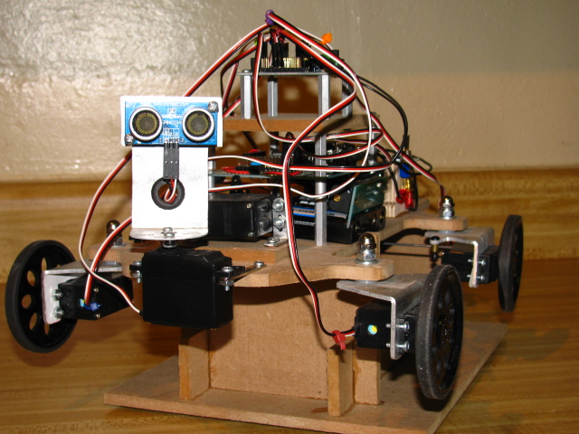
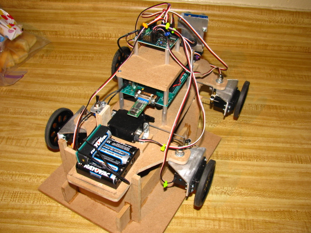
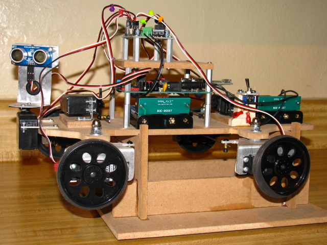
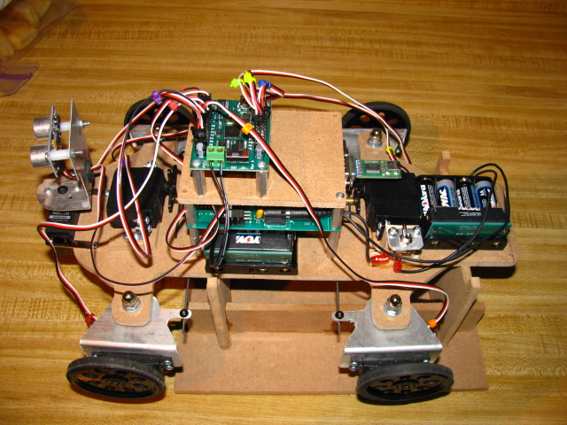
Well I thought I would share one of my older robots, “Bad Hair Day”, for all the BS2 guys out there. I call it “Bad Hair Day” because of all the wires going everywhere. The chassis and metal motor brackets were designed and made by me. The robot has 4 wheel drive and 4 wheel steering being guided by a lone Ping sensor. I first started with a BOE but soon moved to a Super Carrier board with a BS2. Because of the traces on the Super Carrier Board I have access to all 16 pin either through 3 pin headers or sockets (I will do a post on how to make it later on). To take a huge load off the BS2 in controlling 7 servos I added the Propeller Servo Controller. For power I am using two Parallax battery packs with the boosters added. One is for the control board and ping sensor the other just for powering the servos through the servo controller. Note I added a switch to the board power supply because the Super Carrier board doesn’t have a power switch.
Future additions will include one battery source through recharable RC type battery, a rear Ping, bump sensors on front (you will see why they’re needed in the video), compass, GPS and whatever else I come up with. I know what you’re thinking, the BS2 can’t handle it, but I have a future surprise planned.
In the video I left the errors in to show the issues of running on only one ping. I have also posted the code I am running the robot on to help others learn from what I have done. Please realize that this is version 4. I found it very interesting learning how to work within the memory and variable limits of the BS2 especially in storing commands for controlling the servos.
Parts List – Most Items are from Parallax
4 – Continuous Rotation Servos with wheels
3 – Standard Servos
2 – Battery Packs with Boosters
1 – Super Carrier board (added items: 3 pin headers, sockets, button switch for starting program running)
1 – USB to Serial Adaptor
1 – Basic Stamp 2
1 – Propeller Servo Controller Board
1 – Ping Sensor
1 – Homemade Ping Sensor Mount modeled right from Parallax’s design
1 – Homemade chassis, servo motor mounts, and steering links
1 – Toggle switch and post
1 – Work Stand, I think every robot needs a good work stand. A work stand makes it very easy work on the robot and test code. See pictures below.
Hope you enjoy! If you have any questions don’t hesitate to post them. Posting is better than a PM because others can benefit from the discussion.
As with my other designs I'm setting up my woodshop to start making the chassis and components and sell them as kits.
Video link
Tony
Post Edited (Tony B.) : 5/18/2010 2:35:40 PM GMT
Future additions will include one battery source through recharable RC type battery, a rear Ping, bump sensors on front (you will see why they’re needed in the video), compass, GPS and whatever else I come up with. I know what you’re thinking, the BS2 can’t handle it, but I have a future surprise planned.
In the video I left the errors in to show the issues of running on only one ping. I have also posted the code I am running the robot on to help others learn from what I have done. Please realize that this is version 4. I found it very interesting learning how to work within the memory and variable limits of the BS2 especially in storing commands for controlling the servos.
Parts List – Most Items are from Parallax
4 – Continuous Rotation Servos with wheels
3 – Standard Servos
2 – Battery Packs with Boosters
1 – Super Carrier board (added items: 3 pin headers, sockets, button switch for starting program running)
1 – USB to Serial Adaptor
1 – Basic Stamp 2
1 – Propeller Servo Controller Board
1 – Ping Sensor
1 – Homemade Ping Sensor Mount modeled right from Parallax’s design
1 – Homemade chassis, servo motor mounts, and steering links
1 – Toggle switch and post
1 – Work Stand, I think every robot needs a good work stand. A work stand makes it very easy work on the robot and test code. See pictures below.
Hope you enjoy! If you have any questions don’t hesitate to post them. Posting is better than a PM because others can benefit from the discussion.
As with my other designs I'm setting up my woodshop to start making the chassis and components and sell them as kits.
Video link

Tony
Post Edited (Tony B.) : 5/18/2010 2:35:40 PM GMT


Comments
▔▔▔▔▔▔▔▔▔▔▔▔▔▔▔▔▔▔▔▔▔▔▔▔
·"If you build it, they will come."
It’s interesting that you asked that question because that was one of the original design ideas for this robot. When I was building/designing the chassis my dad and I one Sunday afternoon worked on the pivoting in one place and realized it wasn't going to work with this chassis. We determined that the reason it wouldn't work on this chassis, as I had thought, was because the pivot points for the four wheels must form a square. Thus all wheels would be following the same radius when pivoting. As it is now they wouldn't, that is, the robot is longer than it is wide. Other than that change all you would need is two more steering servos. Thus you would have a servo for each wheel.
Thanks for reminding me that I was going to build another chassis to work this out. I'll work on the pivoting in one place this week.
Thanks
Tony
Looks and works great! I love the video with all the real life bumps and situations. I seems to get itself out of trouble pretty well.
Also - you don't have to sell me on a work stand - I think it always a great idea.
▔▔▔▔▔▔▔▔▔▔▔▔▔▔▔▔▔▔▔▔▔▔▔▔
Whit+
"We keep moving forward, opening new doors, and doing new things, because we're curious and curiosity keeps leading us down new paths." - Walt Disney
humanoido
I think you could turn in place with a rectangular chassis, but you would have to steer each wheel independently. With out that ability (that is independent steering for each wheel) I don't believe even the square chassis configuration would work.
▔▔▔▔▔▔▔▔▔▔▔▔▔▔▔▔▔▔▔▔▔▔▔▔
Whit+
"We keep moving forward, opening new doors, and doing new things, because we're curious and curiosity keeps leading us down new paths." - Walt Disney
·
Martin_H, you are correct I am only using one Ping sensor for collision detection.· I hope to develop, if possible, a scanning routine to better evaluate the environment while the robot is moving.· I hope this will help detect objects that are missed when the ping just points forward and the angle from the ping to object doesn't allow a return signal.· Also, a couple of wire bumpers in front of the wheels would help as well.
·
Whit, you are correct that we would need a steering servo on each wheel.· That was in the original design.· To clarify the issue with the rectangle chassis, to get the rectangle chassis to turn in place you would need (I believe haven't tested yet) I large amount of toe in to match the need angle to turn in place.· My Dad and I believed this to be well out of the degrees of movement for a standard servo.· That is why we were led to a square chassis idea.· With the square you would need less degrees of toe in to allow the robot to turn in place because the center would be equal distance from each pivot point· as well as, each pivot point the same distance for the other.· I have included a drawing to help further or just confuse this discussion.· I’m not a math wizard, so I feel the best choice for me is to build a square and rectangle chassis (which I already have)to test the idea.
·
Thanks,
Tony
▔▔▔▔▔▔▔▔▔▔▔▔▔▔▔▔▔▔▔▔▔▔▔▔
Whit+
"We keep moving forward, opening new doors, and doing new things, because we're curious and curiosity keeps leading us down new paths." - Walt Disney
Over in my Mashup Robot thread I posted the code I am currently using for a Ping sweep. I borrowed the idea from the Roaming with BOEbot code. My code looks at -90, -45, 45, 90, and then re-centers to 0 degrees from straight. It returns this array in the scratch pad so the calling program can choose the best direction based upon the measurement and the criteria.