Inductor Question
 Tapperman
Posts: 321
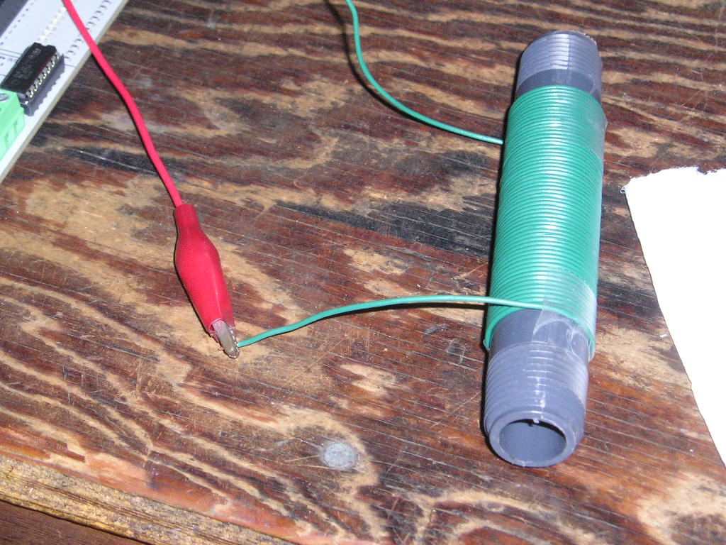
· In reading through the Propeller Education Kit, I happened across the metal detector project.· So I built my own and changed everything (of course).· See attached images.
· But I confused?· If you put a peice of metal thru the center of a coil ... does it increase it's inductance?
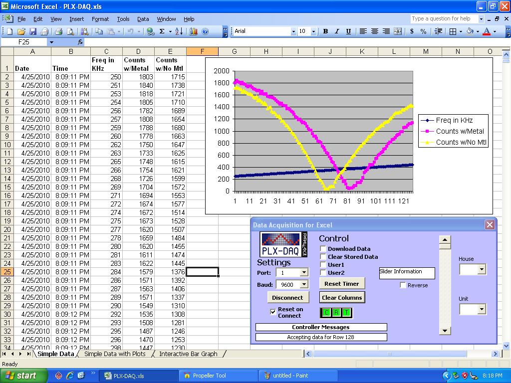
· When I tested it .. the frequency increased with the metal object in the center of the coil, shouldn't it decrease?
· But I confused?· If you put a peice of metal thru the center of a coil ... does it increase it's inductance?
· When I tested it .. the frequency increased with the metal object in the center of the coil, shouldn't it decrease?


Comments
www.lammertbies.nl/electronics/PI_metal_detector.html
Again, I don't know what I"m talking about but I would be very interested to hear what a forum guru has to say about this problem.
I remember as a kid, my dad had a tool--a rod that had a piece of iron on one end and a piece of brass on the other. While injecting an RF signal into the IF stage of a radio receiver, tube receiver of course, he would place one end or the other near coils in an IF stage while measuring the output level of the stage with an oscilloscope. If the level would increase with one or the other metals, he would know which way to tune the coil to get maximum gain. If the signal dropped with either end near the coil, then the coil would be properly set.
.Steve
some time ago I experimented with these impressing possibilities of the prop too and studied patents and electronics of metal detectors.
http://forums.parallax.com/forums/default.aspx?f=21&m=206239
If the frequency of the LC-circuit is low (<18kHz, as far as I remember), you can discriminate the metal type with the direction of the frequency shift.
Christof
▔▔▔▔▔▔▔▔▔▔▔▔▔▔▔▔▔▔▔▔▔▔▔▔
Leon Heller
Amateur radio callsign: G1HSM
Post Edited (Leon) : 4/26/2010 10:50:19 AM GMT
Right now, I need to remake the inductor to lower the tank center freq, as I am both geographically close to a 590 KHz AM transmitter and my center freq of my LC tank is in the neighborhood of 400 KHz.· It's working, but does have 'jitter' from RF sources.
I started out on this loop design with the intension of replacing a pot to collect throttle data from.· As every pot I encounter gets dirty to quickly (and I'm not so sure some of that 'noise' isn't being rubbed off by the wiper contacting the carbon film?)
In addition, my throttle needs to be centered (when not touched).· I'm currently building the device in a U-Channel and then place a spring in front and behind the lever .. so as to return-to-center when I let go!· However, using a pot means I have to use much stronger springs!· The manufactures construct 'off-the'shelf' pot's with a built in drag setting (keeps them from moving on a panel, once a desired position is set).
So if the inductor works (software to track the local minima - I haven't written the code for this part yet), I can put the whole thing in a metal soup can (perhaps) to stop RF affecting the loop.··And the metal object goes thru the center of the PVC pipe I wound the loop on, with near zero drag!
Well ... on that note, I'm going to hunt up a peice of brass and aluminum, and go study the affects?
·
What you are observing is correct and coincides with the Propeller Education Kit Lab on page 177 of the PDF.
As mentioned, the result that you are seeing has to do with the permeability of the metal within the coil.
Using the attached simple circuit, a quarter in the presence of the coil causes the frequency to go up (as observed, but not as expected), while a ferrite rods causes the frequency to go down (as expected).
So, in answer to your question... "If you put a piece of metal thru the center of a coil ... does it increase it's inductance?" ... depending on the metal yes and no
That said, I think there are some other things going on with this setup. Since we are dealing with an Air-core coil, the addition of ANY metal should cause an increase in the permeability thus causing the inductance to also increase yet our observations show otherwise.
If you look at the attached circuit again and replace the coil with a resistor instead. Lowering the resistance you will cause the frequency on the output to increase.
Applying that same thinking to a coil would mean that the effective impedance decreases with the presence of a quarter but increases with the presence of a ferrite rod.
Remember adding metal to the presence of a coil is basically like shorting out the secondary coil on a transformer. Doing so will cause a higher current demand (<- lower resistance/impedance) on the primary coil.
Hope this helps.
▔▔▔▔▔▔▔▔▔▔▔▔▔▔▔▔▔▔▔▔▔▔▔▔
Beau Schwabe
IC Layout Engineer
Parallax, Inc.
Try not to spin-out
PS - 1st picture is of an aluminum driver (I think) and the pink line shows the Fc went up!· And in the 2nd photo the Fc went down.· And I'm holding a 1/4"·Square Solid Iron stock.· It's amazing!
Post Edited (Tapperman) : 4/27/2010 8:52:21 PM GMT
What is my source? - Hmmm, that's a tough one. Other than 23+ years of experience and directly observing what happens.
Seriously, it took me awhile to initially reply to this post. I had to do a little research myself, because you are right this inductor phenomenon seems very counter intuitive. What I found, and I think is what is being observed here, is the reason why laminate cores are used in transformers and solid iron cores are not.
Reference:
http://en.wikipedia.org/wiki/Transformer
"Early transformer developers soon realized that cores constructed from solid iron resulted in prohibitive eddy-current losses" <- This excerpt from the above wiki page I believe is a key factor to the observation we are seeing.
As always I am open to any ideas someone else might have that perhaps explains this better than I can.
In the observation here:
- Since the quarter is solid metal, in the presence of a coil, the quarter acts like a shorted secondary coil.
- The same effect as seen with the quarter can be observed with a single loop of wire that has its ends shorted together. (You can even have a single loop of wire with a switch on it to see this)
- Both have an effect of placing inductors in parallel thus DECREASING the inductance.
- Using a ferrite rod made from non-conductive magnetic ceramic materials, in the presence of a coil, has an effect of placing inductors in series thus INCREASING the inductance.
Note:
- inductors in parallel decrease inductance
- inductors in series increase inductance
▔▔▔▔▔▔▔▔▔▔▔▔▔▔▔▔▔▔▔▔▔▔▔▔
Beau Schwabe
IC Layout Engineer
Parallax, Inc.
Post Edited (Beau Schwabe (Parallax)) : 4/28/2010 3:10:01 AM GMT