Xbee testing anomaly - BOTH ISSUES RESOLVED!
 Wildatheart
Posts: 195
Attached are 2 BS2 programs that I've been running on 2 BS2 OEM boards with 2 Xbee Pro's - one sitting atop a USB 3/5 volt adapter board and the other sitting atip a (non USB) 3/5 volt adapter board. If someone has XBee to Xee communication capabilities through OEM boards or through other stamp setups, would you please be willing to load and run these programs to check my findings.
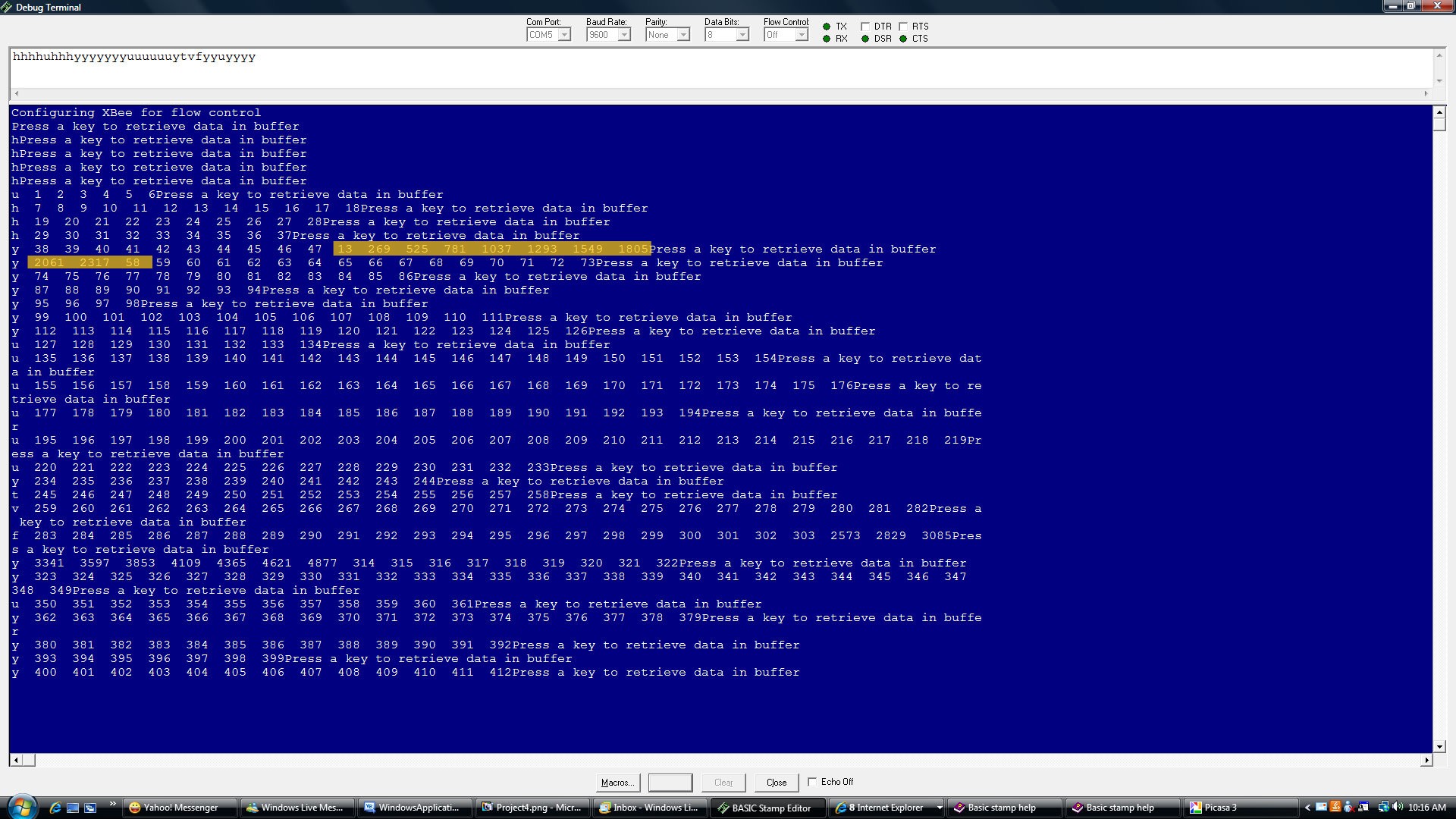
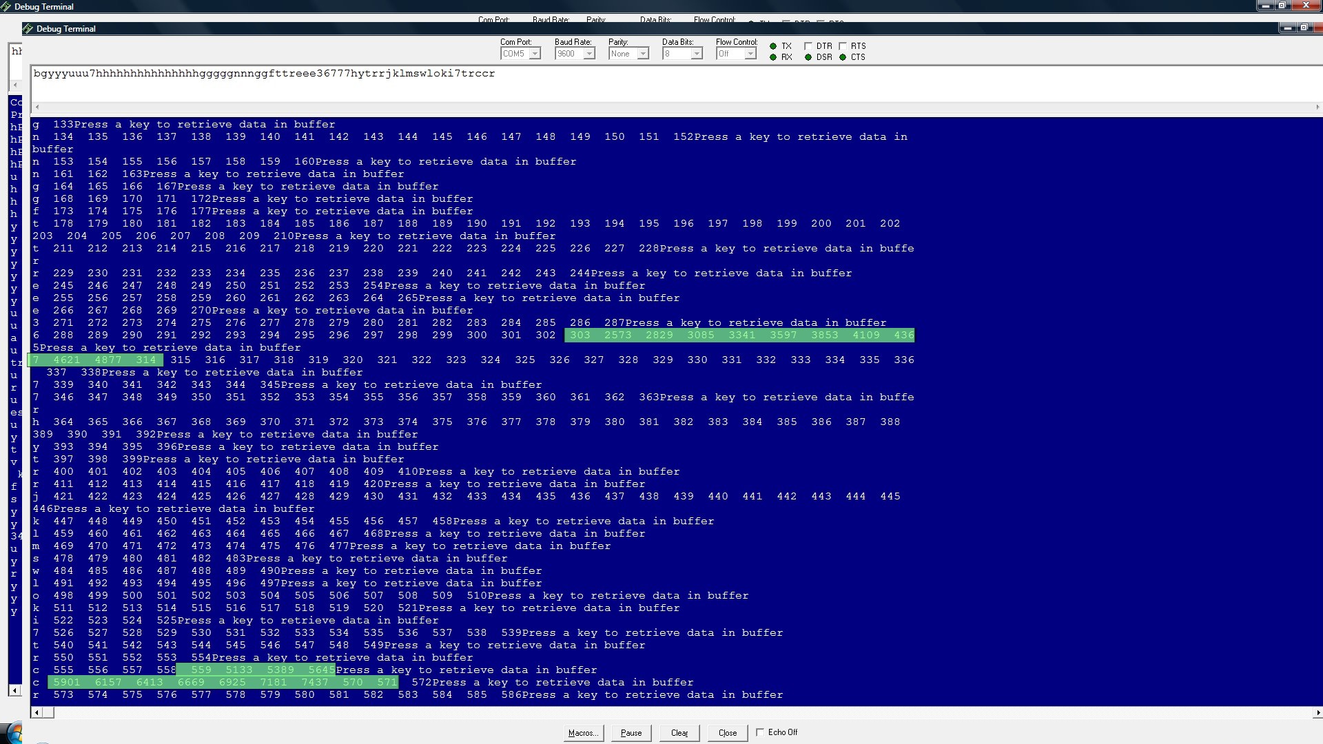
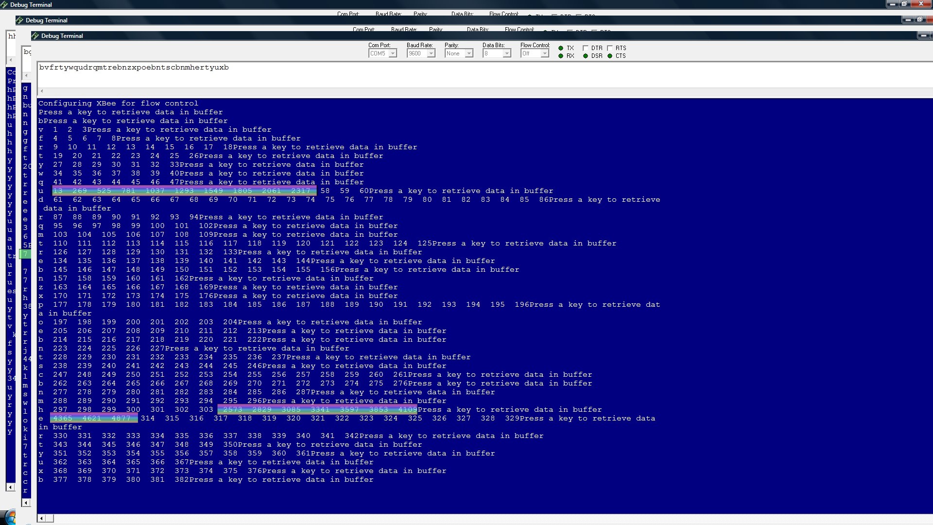
Also attached are 3 screen-shots of my DEBUG display. Would you note the anomalies occuring at counts 47, 303, and 559. I'd be curious to know if your test runs confirm these results.
There is something unique about the number 47 - at that (or about that) point is the limit of the Xbee buffer when using flow control. From that count on, the anomalies occur 256 cycles apart. 256... an interesting, and otherwise uniquely significant number
Post Edited (Wildatheart) : 4/28/2010 5:03:09 PM GMT


Comments
First, you are using the DEC modifier only the HIGHBYTE - I would not use it on either (and don't send CRs)
·· SEROUT TX,Baud, [noparse][[/noparse]X.HIGHBYTE, x.LOWBYTE]
·· SERIN RX\RTS, Baud,100,Timeout,[noparse][[/noparse]x.HIGHBYTE, x.LOWBYTE]
Second, you are using the baud·variable·sometimes and hardcoded "84" other times - use the variable.
(This is only important if you are using stamps that have different baud number requirements)
Third, your Motor subroutine is taking a long time and causing things to get out of sync.
If you comment out these two lines you will get reliable values received:
· ' DEBUG "Press a key to retrieve data in buffer", CR
· ' DEBUGIN X
·· ' IF x = 50 THEN GOSUB Motor················ ' Cycle bilge pump
· ·' IF x = 50 THEN GOTO Main
You need a more robust approach. Have the sending stamp send a request code (like 50) and then wait for the receiving stamp to reply with a code indicating that the Motor routine was executed· before sending another request.
Post Edited (ronczap) : 4/24/2010 7:40:23 PM GMT
I would suggest several things:
First, you are using the DEC modifier only the HIGHBYTE - I would not use it on either (and don't send CRs)
SEROUT TX,Baud, [noparse][[/noparse]X.HIGHBYTE, x.LOWBYTE]
SERIN RX\RTS, Baud,100,Timeout,[noparse][[/noparse]x.HIGHBYTE, x.LOWBYTE]
Various combinations of including or excluding the DEC and CR produced less than the expected results (and in some cases, none at all).
Second, you are using the baud variable sometimes and hardcoded "84" other times - use the variable.
(This is only important if you are using stamps that have different baud number requirements)
Good programming form requires consistency – thanks for the suggestion. The program was changed to reflect this consistency.
Third, your Motor subroutine is taking a long time and causing things to get out of sync.
The Motor subroutine was thrown in purposefully to cause the out of sync condition. It was expected that the receiving Xbee buffer would overflow and the desired result was to watch the resumption of order after the discontinuity. I understand that the Xbee has a buffer of about 45 bytes.
If you comment out these two lines you will get reliable values received:
' DEBUG "Press a key to retrieve data in buffer", CR
' DEBUGIN X
These statements were also purposefully included for watching flow control between the two radios. The simple “transmit and receive” without flow control works perfectly but the entire point of this little test program is to gain experience with “flow control” between the two setups.
' IF x = 50 THEN GOSUB Motor ' Cycle bilge pump
' IF x = 50 THEN GOTO Main
Fully removing these two statements, removing the HB25 initialization, and entirely removing the Motor subroutine made no difference from the anomalies shown in the original screen shots.
You need a more robust approach. Have the sending stamp send a request code (like 50) and then wait for the receiving stamp to reply with a code indicating that the Motor routine was executed before sending another request.
When a program that reaches beyond the purpose of “testing” is considered, there are certainly better ways (as you suggested) to single out events in ways other than that which is being used here.
Post Edited (Wildatheart) : 4/25/2010 6:10:57 PM GMT
The attached programs worked with consistent results. I had both stamps connected to serial ports displaying DEBUG values.
Received values reflected sent values.
>>>NOTE I use different pins for RX,TX,RTS in my code
Regarding your comment… “I understand your need/desire to buffer incoming data but believe a request/response scenario is more dependable. Most communication protocols depend on acknowledgement and/or CRC checks.”
First, a key feature of the Xbee is supposed to be its ability to transparently send and receive data without error. Various forms of our programs have confirmed error free transmission with a high degree of confidence. Then, our DEBUG display confirms that the bs2 is feeding the transmitter good data, and we’ve also confirmed that a second bs2 can receive and display good data under certain conditions (in the absence of DEBUGIN). So, the “request/response scenario” isn’t in question unless you’re expanding that notion to include continuous communication in the form of a “send now-receive now”/”receive now-send now” exchange between the TX setup to the RX setup.
Your revised RX program comments out the DEBUGIN statement and therefore does allow for accurate and continuous processing of the data as it’s available.
But… DEBUGIN is used to transfer program control, much the same as a switched input, or ‘jump-to subroutine on receipt of predefined data ’. In those cases too, continuous processing of the RX data would be interrupted and we should find ourselves with a similar problem. I think we can’t arbitrarily comment out something that ordinarily performs a valid function to get other work done.
Also… I don’t think this is a buffer or a communication problem. A buffer problem should reflect frequent and sporadically disjointed data values, and a communication problem would likely not display itself with such order as exists. The original screen shots depict unique points, and p0atterns of discontinuity in the processing of otherwise very orderly data. Very predictable.
FYI.. a hard wired momentary switch input using the BUTTON command (in lieu of DEBUGIN) gives the same disconnected results shown in the original screen shots.
I’m curious… is there a good reason to comment out the DEBUGIN or BUTTON control?
I have attached two programs that demonstrate the issue.·
The commented out serin/serout commands·reflect what you were doing originally and the active code works.
However, if you execute the Motor routine, transmitted bytes can be dropped and you combine bytes from two adjacent transmitted words...
NOTE: I use different pins fro RX,TX and RTS and I use PORT directives
The SEROUT and SERIN commands·can be complex·when using modifiers like DEC.·
From the Basic Stamp manual:
SERIN (pg 399):
The decimal formatter is designed to seek out text that represents decimal numbers. The characters that represent decimal numbers are the characters “0” through “9”. Once the SERIN command is asked to use the decimal formatter for a particular variable, it monitors the incoming serial data, looking for the first decimal character. Once it finds the first decimal character, it will continue looking for more (accumulating the entire multidigit number) until is finds a non-decimal numeric character. Keep in mind that it will not finish until it finds at least one decimal character followed by at least one non-decimal character.
SEROUT (pg 420)
SEROUT 1, 16780, [noparse][[/noparse]DEC 65]
Notice the decimal formatter in the SEROUT command. It is the “#” (for the BS1) or “DEC” (for all BS2 models) that appears just to the left of the number 65. This tells SEROUT to convert the number into separate ASCII characters which represent the value in decimal form. If the value 65 in the code were changed to 123, the SEROUT command would send three bytes (49, 50 and 51) corresponding to the characters "1", "2" and "3".
Good luck handling the buffering aspect...
▔▔▔▔▔▔▔▔▔▔▔▔▔▔▔▔▔▔▔▔▔▔▔▔
Chris Savage
Parallax Engineering
·
ronczap’s information re serial transmission form is significant. His suggested RX and TX programs allow for orderly TX/RX HEX data transmission if all the micro is doing is receiving and displaying data.
Okay… I modified his suggested programs to accommodate my hardware while leaving his program substantially intact. In addition to those minor modifications I added a subroutine that intentionally caused a 3 second delay for the processing of the data being received by the Xbee. Screenshot (attached) displays the disconnected data after returning from the delay.
Although my earlier forms of the programs generated anomalies only at counts 48, 304, 560, etc., they permitted an orderly resumption of the received and buffered data after a delay due to waiting on a switched input, a program delay, or other general processing.
I’ve been communicating with others who are close to the hardware/software under consideration. I do hope they’ll weigh in (or I’ll report back) when this situation is fully understood.
In the meantime, please continue submitting your thoughts on the subject. I’d be happy to test any and all ideas, but please include the need for the micro to do more than just send and receive data.
Revised RX and TX programs are attached.
Post Edited (Wildatheart) : 4/28/2010 4:25:38 AM GMT
The reason the original program showed the anomalies was due·to·the way the DEC modifier works on the serin - to "seek out text that represents decimal numbers."
Each time the LOWBYTE switches from 0x2F to 0x30· (e.g. 47 to 48 and 303 to 304).
That is is because 0x30 is an ascii zero "0" which the DEC in the receive program detected.
The debug data values returned to normal after the 0x39 (ascii "9") when decimal 58 was transmitted - the vale 2317 (0x090D) was the 09 and the CR bytes mistakenly combined.
The same thing after 303 0x012F·- after 559 (0x022F) ·- after 815 (0x032F) etc etc.
Every time the lowbyte·changed from·0x2F to 0x30, the problem would occur.
To prevent combining bytes from two different WORDs after a processing delay, you might consider sending a control word·or byte sequence (between data words)·that could be used to synch back up.
- Ron
Post Edited (ronczap) : 4/28/2010 5:03:01 AM GMT
Please see my previously attached screenshot for the disconnection.
-gordon
Post Edited (Wildatheart) : 4/28/2010 5:25:12 AM GMT
With this it is now possible -
...to receive continusously flowing data
...break from processing that data based on either a particular data or other asynchronous input
...go do some other micro work
...return and resume processing of the orderly buffered data
Thanks again for your, and all other suggestions regarding this matter. -gordon