

PUPPY Prop module for prototyping - now with fast 12-bit ADC/DACs (was Prop Kwi
 Peter Jakacki
Posts: 10,193
Peter Jakacki
Posts: 10,193
Normally I don't worry about DIP prototyping modules but I am looking at using a local pcb service for some cheap & quick single-sided pcbs (motherboards) and I thought that if I had a few more smd modules (daughter boards, double-side plated through) then I could knock out some special pcbs and testers real easy. Normally I have used the local pcb service for 5-day double-sided PTH + masks etc prototype panels (large). Anything that I can fit on a large panel I can have for one set price but this usually costs around $400 and actually takes closer to 7 working days. But if I want a simple single sided pcb panel, no masks, then this is much cheaper and can be had in 2 to 3 days.
So if I want a Propeller design admittedly I could use the DIP Props but then I always want the normal EEPROM + crystal etc. Looking at some of the modules I design and manufacture I thought why can't I use this format to mount all the Prop goodies on including caps for the sigma-delta stuff. So that's what I did and in just a couple of hours I have laid out 95% of the pcb, the other 5% will take just as long (or longer). The 3D view looks good but there is nothing like a mock-up when you can do it and I happened to have some blank pcb modules here so I did a mock-up.
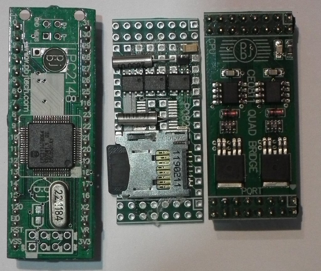
Here is a photo of the mock-up with another module in the same format next to it and compared to a 40-pin DIP module as well. I can get 25 I/O + 2 for the I2C plus 2 for the RX/TX as well as the RESET and power, that's 32 pins. I have included a micro-SD, 4MB serial dataflash, RTC with supercap under the pcb, and LDO regulator so I can run it from 3 to 9V easily. There is actually a small area for a PropPlug to go into as well. The QFP Prop is under the pcb.
What do you think, would anyone be interested in these? I will probably end up with far more than I could use so I will make them available assembled.
EDIT: This module is double-sided and plated through and packed with smd goodies (including ADC) just so that I can use single-sided "motherboards" easily.
April 25, 2010 - created webpage for this module at docs.google.com/Doc?id=ddgq8k4b_5gtvcrfhh
This page will be updated regularly.
▔▔▔▔▔▔▔▔▔▔▔▔▔▔▔▔▔▔▔▔▔▔▔▔
*Peter*
Post Edited (Peter Jakacki) : 4/27/2010 3:03:48 AM GMT
So if I want a Propeller design admittedly I could use the DIP Props but then I always want the normal EEPROM + crystal etc. Looking at some of the modules I design and manufacture I thought why can't I use this format to mount all the Prop goodies on including caps for the sigma-delta stuff. So that's what I did and in just a couple of hours I have laid out 95% of the pcb, the other 5% will take just as long (or longer). The 3D view looks good but there is nothing like a mock-up when you can do it and I happened to have some blank pcb modules here so I did a mock-up.
Here is a photo of the mock-up with another module in the same format next to it and compared to a 40-pin DIP module as well. I can get 25 I/O + 2 for the I2C plus 2 for the RX/TX as well as the RESET and power, that's 32 pins. I have included a micro-SD, 4MB serial dataflash, RTC with supercap under the pcb, and LDO regulator so I can run it from 3 to 9V easily. There is actually a small area for a PropPlug to go into as well. The QFP Prop is under the pcb.
What do you think, would anyone be interested in these? I will probably end up with far more than I could use so I will make them available assembled.
EDIT: This module is double-sided and plated through and packed with smd goodies (including ADC) just so that I can use single-sided "motherboards" easily.
April 25, 2010 - created webpage for this module at docs.google.com/Doc?id=ddgq8k4b_5gtvcrfhh
This page will be updated regularly.
▔▔▔▔▔▔▔▔▔▔▔▔▔▔▔▔▔▔▔▔▔▔▔▔
*Peter*
Post Edited (Peter Jakacki) : 4/27/2010 3:03:48 AM GMT
1024 x 864 - 206K
869 x 406 - 39K
Comments
▔▔▔▔▔▔▔▔▔▔▔▔▔▔▔▔▔▔▔▔▔▔▔▔
*Peter*
Kevin
▔▔▔▔▔▔▔▔▔▔▔▔▔▔▔▔▔▔▔▔▔▔▔▔
New ICON coming, gotta wait for the INK to heal, now we have colour!
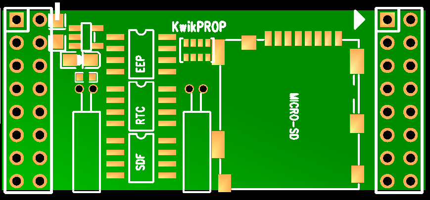
KwikProp Specifications:
- 29 I/O (including I2C and RX/TX)
- Propeller P8X32A QFP
- 24LC256 32K byte EEPROM
- PCF8563 RTC + 0.047F supercap
- 25VF032 4M byte SPI Flash (or similar)
- microSD socket - push-push type (unpopulated)
- C8051F334 peripheral ADC CPU
- -- 8 channels 10-bit A/D with reference + temperature (P16..P23)
- -- In-circuit programmable from Propeller
- LDO regulator 3..9V input
- 1.8" x 0.8" module
- Dual 8x2 pins (0.1" pitch)
- PropPlug interface
PINOUTSHow much? I'm trying to keep the price down but a conservative estimate I'd expect to sell them for around $48 (US) one off.
Availability? I want them yesterday so I am aiming for protos in 2 weeks and production in 3-4 weeks.
EDIT: Added revised pcb layout
▔▔▔▔▔▔▔▔▔▔▔▔▔▔▔▔▔▔▔▔▔▔▔▔
*Peter*
Post Edited (Peter Jakacki) : 4/23/2010 2:33:01 PM GMT
Bill
▔▔▔▔▔▔▔▔▔▔▔▔▔▔▔▔▔▔▔▔▔▔▔▔
*Peter*
▔▔▔▔▔▔▔▔▔▔▔▔▔▔▔▔▔▔▔▔▔▔▔▔
*Peter*
How do your boards connect together?
▔▔▔▔▔▔▔▔▔▔▔▔▔▔▔▔▔▔▔▔▔▔▔▔
May the road rise to meet you; may the sun shine on your back.
May you create something useful, even if it's just a hack.
▔▔▔▔▔▔▔▔▔▔▔▔▔▔▔▔▔▔▔▔▔▔▔▔
Lots of propeller based products in stock at affordable prices.
If you change to 2x10 headers, you will gain quite a bit of versatility while keeping your module small.
As far as adding ADC, here's my 76 Guinea Francs... it will be excellent for prototypers using ADC, but will limit the module as a "universal" Kwik propeller module unless you have a way to no-load the chip and have P16-P23 accessible. I can't tell if your header pins go to both the ADC and the prop which would nullify that comment.
This actually reminds me of my $25 "M44D40" board that I started last year (pic attached). Needs a few finishing touches before it can be put to copper.
▔▔▔▔▔▔▔▔▔▔▔▔▔▔▔▔▔▔▔▔▔▔▔▔
Andrew Williams
WBA Consulting
WBA-TH1M Sensirion SHT11 Module
Special Olympics Polar Bear Plunge, Mar 20, 2010
I cannot tell from the pcb... did you manage to get the 64KB footprint EEPROM in ?
Yes, the header would have been nicer to be compatible with other footprints, but as you can all see, the pcb is way to tight for that.
▔▔▔▔▔▔▔▔▔▔▔▔▔▔▔▔▔▔▔▔▔▔▔▔
Links to other interesting threads:
· Home of the MultiBladeProps: TriBlade,·RamBlade,·SixBlade, website
· Single Board Computer:·3 Propeller ICs·and a·TriBladeProp board (ZiCog Z80 Emulator)
· Prop Tools under Development or Completed (Index)
· Emulators: CPUs Z80 etc; Micros Altair etc;· Terminals·VT100 etc; (Index) ZiCog (Z80) , MoCog (6809)·
· Prop OS: SphinxOS·, PropDos , PropCmd··· Search the Propeller forums·(uses advanced Google search)
My cruising website is: ·www.bluemagic.biz·· MultiBlade Props: www.cluso.bluemagic.biz
The pins that are labeled P0..P24 are indeed the same pins as the Prop chip itself, hence the label. The ADC pins sit in parallel with P16..23 so no matter what the Prop pins is doing the ADC is running independently and without interference which by the way is very easy to access via I2C with dedicated addresses for each channel (disable feature via an option register). This makes it very fast to access so you only need to issue the I2C device address and read the input that you want in the very next access with any sequential accesses delivering more information on that channel such as the average/min/max etc.
Sigma delta caps are still in place for P0 and P2 while the feedback resistors can be added externally. The caps won't affect normal digital output switching or even most input signals. Being on the bottom of the PCB they can be removed quite easily with a wipe of a hot iron.
One of the reasons I chose this pcb format is because I find the 40-pin DIP restrictive plus those poor tracks are routed quite a distance and soak up valuable pcb real-estate that could be used for something other than just copper. Another reason too is that the microSD socket would not fit on a DIP pack but as you can see from the layouts it fits beautifully here. The pcb is designed to be side by side stackable without any gaps and I also have many I/O modules including that 100kHz 10A quad half-bridge module I mentioned in the Sandbox a few weeks ago. I also mentioned my original design that used this module format in
http://forums.parallax.com/showthread.php?p=791643
The pinout on this header is not compatible even with my I/O modules because they are very different beasts as the right side is normally dedicated to power switching and the left side to Prop I/O. You can glimpse from the pcb transparency that the Prop pins just flow to the header pins without so much as an excuse me.
As to the manufacturing of them I don't have any problems as I have had many years of experience with surface mount and these packages etc and I have no problem building the prototypes and initial production myself. If there is enough demand for it then I have people locally that can do pick and place but for these tiny boards I will need to do a run of at least 1,000 to make it economical to cover setups bearing in mind too that reels have quantities like 3,300 chips as in the case of the EEPROM so that's a lot of money upfront which "might" eventually pay for itself but would it be worth the trouble? Keep it simple I say, don't stick your neck out too far, enjoy each day.
▔▔▔▔▔▔▔▔▔▔▔▔▔▔▔▔▔▔▔▔▔▔▔▔
*Peter*
I have added a watchdog function from the PPC to the Propeller. If the Prop activates it then it doesn't go away until the Prop gets reset, one way or another.
▔▔▔▔▔▔▔▔▔▔▔▔▔▔▔▔▔▔▔▔▔▔▔▔
*Peter*
docs.google.com/Doc?id=ddgq8k4b_5gtvcrfhh
▔▔▔▔▔▔▔▔▔▔▔▔▔▔▔▔▔▔▔▔▔▔▔▔
*Peter*
Bill
Where there is space then I see the 64KB version as a no-brainer for minimal cost, but I think size is important for your module too, so 32KB is fine.
BTW Why did you choose an 8051 overa MC9S08, PIC or AVR? Just asking as I am curious if it has something special or it is because you already use them.
▔▔▔▔▔▔▔▔▔▔▔▔▔▔▔▔▔▔▔▔▔▔▔▔
Links to other interesting threads:
· Home of the MultiBladeProps: TriBlade,·RamBlade,·SixBlade, website
· Single Board Computer:·3 Propeller ICs·and a·TriBladeProp board (ZiCog Z80 Emulator)
· Prop Tools under Development or Completed (Index)
· Emulators: CPUs Z80 etc; Micros Altair etc;· Terminals·VT100 etc; (Index) ZiCog (Z80) , MoCog (6809)·
· Prop OS: SphinxOS·, PropDos , PropCmd··· Search the Propeller forums·(uses advanced Google search)
My cruising website is: ·www.bluemagic.biz·· MultiBlade Props: www.cluso.bluemagic.biz
1) It could fit in the tiny corner due to the 20-pin QFN
2) I have used them before as PPCs
I really wanted to use the new LPC111x chips as they are cheaper and faster and a full 32-bits but they just wouldn't fit.
The way I use 32K of EEPROM in some systems is to lock in a bootloader that reads from the serial Flash and/or the SD card for an autostart file. I can reload the firmware reliably via various methods and always have my own bootloader that I can count on. This means that during development the Prop tool just loads the EEPROM as normal but once testing is done the EEPROM holds the bootloader which loads in the application from serial Flash or SD (both very fast methods) and it can receive new firmware from the SD or other communications links.
If it were an absolute minimal system without these other chips then a 64K EEPROM would make a lot of sense. However, I did say that I would use the 64K devices but in a DFN pack so that they would fit but not at the expense of compromising the design. It turned out that the common serial Flash chips were also wide so I had to make an adjustment to the artwork for this but fortunately there was a tiny bit of room in this part of the pcb. If it were a choice to have a wide footprint for the 64K EEPROM and no serial Flash then I would not take that course, but rather emphasize the on-board memory capacity of the serial Flash. You can't rely on the microSD as that can be removed, but the serial Flash is always there.
@Bill: Wouldn't the 4M bytes of serial Flash allow you to load in umpteen splash screens and be able to read out much much faster than a slow 400kHz EEPROM?
▔▔▔▔▔▔▔▔▔▔▔▔▔▔▔▔▔▔▔▔▔▔▔▔
*Peter*
I too have a boot loader but it only boots from the SD card - with my setup, there is no point to not have a uSD.
What you have is a nice small module so we will see how it goes. You have your own use for it anyway.
▔▔▔▔▔▔▔▔▔▔▔▔▔▔▔▔▔▔▔▔▔▔▔▔
Links to other interesting threads:
· Home of the MultiBladeProps: TriBlade,·RamBlade,·SixBlade, website
· Single Board Computer:·3 Propeller ICs·and a·TriBladeProp board (ZiCog Z80 Emulator)
· Prop Tools under Development or Completed (Index)
· Emulators: CPUs Z80 etc; Micros Altair etc;· Terminals·VT100 etc; (Index) ZiCog (Z80) , MoCog (6809)·
· Prop OS: SphinxOS·, PropDos , PropCmd··· Search the Propeller forums·(uses advanced Google search)
My cruising website is: ·www.bluemagic.biz·· MultiBlade Props: www.cluso.bluemagic.biz
Bill
There is no room for anything else on this pcb but I did manage to squeeze in the RX/TX lines from the PPC chip so that this can actually form a fully-buffered cogless serial channel accessed through I2C. Decoupling caps are evenly distributed and have very short and generous paths to the chips.
I am wondering whether to load these modules with 6MHz crystals to take advantage of both overclocking plus USB support. The I2C lines are shared with SPI as only one device will be used at a time so there is one cog that handles the SD card, the Flash, the EEPROM, the RTC, the PPC, plus any other external I2C device. It is possible for the PPC at boot to load up the EEPROM directly from Flash or SD then release the Prop reset thus making the autoload feature completely transparent to the Prop itself. Alternatively I will probably have a bootloader sitting in EEPROM when this device is not in development mode so that it can decide whether it will run software from the Flash, or the SD etc.
Any feedback is welcome and although I could add improvements to the schematic easily it is a different story trying to route that on the pcb. I will be sending the artwork off tomorrow. Now the sneaky embedded fine print: I will be giving away three of the fully populated and assembled prototypes. If you have an application for one of these modules and this giveaway interests you then drop me an email and tell me a bit about how you would use it and I will select three of these that I think deserve it and the first that you will know of it is when you receive your module in the mail around mid May. I may even be inclined to select more than three, don't we just love this forum(?)
docs.google.com/Doc?id=ddgq8k4b_5gtvcrfhh
▔▔▔▔▔▔▔▔▔▔▔▔▔▔▔▔▔▔▔▔▔▔▔▔
*Peter*
Post Edited (Peter Jakacki) : 4/26/2010 2:23:01 PM GMT
It looks like the 5th pin of the PropPlug connector is for the 5V supply. I've done this also in the same way on many of my little boards. This lets one supply the boards direct from the USB, with a special PropPlug that brings the 5V from USB direct to this 5th pin.
But I'm a bit concerned about this other usage of the 5th pin, suggested by Bill Henning, and implemented also on the GadgetGangster SMD Propeller platform board. They feed 3.3V to the PropPlug over this pin.
You can imagine what happens if a PropPlug with a USB voltage is pluged in a connector that feeds 3.3V....
I think we need some standard here. One solution can be to use a 6th pin for the 5V supply.
Andy
Edit: picture attached
Post Edited (Ariba) : 4/26/2010 2:06:04 PM GMT
I don't quite understand why anybody would be feeding 3.3V to a Prop Plug unless it has something to do with getting around the phantom power problem.
▔▔▔▔▔▔▔▔▔▔▔▔▔▔▔▔▔▔▔▔▔▔▔▔
*Peter*
Post Edited (Peter Jakacki) : 4/26/2010 2:48:35 PM GMT
5 pin 3.3 on SerPlug are used to feed it with power suplay that is needed for SP/MAX 3232 IC.
Regards
Ps. Look on SerPlug thread for details
▔▔▔▔▔▔▔▔▔▔▔▔▔▔▔▔▔▔▔▔▔▔▔▔
Nothing is impossible, there are only different degrees of difficulty.
For every stupid question there is at least one intelligent answer.
Don't guess - ask instead.
If you don't ask you won't know.
If your gonna construct something, make it·as simple as·possible yet as versatile as posible.
Sapieha
Congratulations on a great little design. What you have onboard is a very potent combo. 12 months ago I would have been interested in using it in a commercial product - if it had 12 bit adc (slightly larger 5x5 DFN though). Here's my 2c:-
1) Your stated goal of having simple single sided motherboards is a good one. But bringing the 3v3 rail out to the motherboard would save having to have a second regulator for the majority of applications that don't need more than a few mA
2) Andy's suggestion of 6 pins is a great way to achieve this
3) Is there a reason why the prop plug connection is off the 0.1" grid of the DIL beside it? Shrouded header? Why not go for 3 rows by 8 pins all on a 0.1" grid for flexibility as sometimes the header will need to be brought out via the motherboard, and triple row headers are readily available
4) Got a power led on there? Gotta have a power led to boost sales
Looking at it from a '8051 viewpoint, it looks even more attactive. A 8051 with tv/vga processor on the back. I wouldn't be surprised if you find more people from the 8051 world adopting it than the prop world.
tubular
Post Edited (Tubular) : 4/27/2010 12:36:54 AM GMT
You know that this little puppy (hmmm, maybe I'll call it Puppy Prop instead!!!) is really stacked and maxed but I will see if I can fit an LED into it, one of those little 0603 jobs. I normally put one on my main pcbs and I was going to put one on this module but I forgot (shoot me).
I understand about bringing the 3.3V out especially when you only need a trickle as I have found myself in that situation before. But there is the other side to consider too and that is ensuring that the CPU fed it's own power that's unaffected by other chips either by noise or by over-current conditions. Bear in mind too that this regulator is a small SOT-23-5 pack and you wouldn't want to be drawing too much more current out of it even though it is rated for it as the power dissipation of the package wouldn't really be up to it and there is no room for larger packs. I could extend the Prop Plug header as you suggested though but it's a really tight squeeze as I would like to keep the width of the pcb (0.8") as it is so that it matches my other I/O modules and is stackable. Let me think about it.
BTW, the Prop Plug "connector" wasn't going to be loaded as I would have pins pushed into my Prop Plug cable to sit in the holes during programming. The connector is an "extra" put there for convenience really for use on matrix boards as a motherboard pcb would bring this port out permanently either as RS232 or USB.
12-bit ADC??? Yeah, I know, if only I had the room!! I could do a version without the flash and then I might be able to fit it in. I will think about it as well or I could just get some Puppy Prop prototypes rolling in the meantime.
Thanks for the suggestions, here's a nickel, keep the change
EDIT: I am looking at maybe using a C8051F351 or 353 which are 28-pin 5x5mm packs with either 16-bit or 24-bit 1ksps ADCs. Not so fast but maybe the resolution is better to have. The flash I can cram in using a DFN package. Opinions?
▔▔▔▔▔▔▔▔▔▔▔▔▔▔▔▔▔▔▔▔▔▔▔▔
*Peter*
Post Edited (Peter Jakacki) : 4/27/2010 2:15:03 AM GMT
Upon searching some more there do appear to be 12 bit ADCs available in a 4x4 DFN, eg c8051f530/530a. The power pins don't seem to be compatible with the 334 however (at first glance anyhow)
I wasn't proposing to change the width of your board, just seidle the prop plug up against the 16 pin DIL so its all on 0.1". It looks like its off by 25 mil or so in the X direction, on that earlier rev you posted.
Re the 8051 techs, you would really need to advertise this over on those forums. I don't think 8051 types venture too far
Puppy Prop has a certain catchiness to it. I for one prefer it over KwikProp (or kiwiprop!)
Puppy Prop it is! Good boy, go fetch!
▔▔▔▔▔▔▔▔▔▔▔▔▔▔▔▔▔▔▔▔▔▔▔▔
*Peter*
I think that 75ksps speed is fine since your competition is the MCP320x, which does 50 ksps at 3v. Also the cost of the F912 is about the same as the MCP3208, but about 30% less than the F413.
The F912 has some other interesting features - the ADC can also do 10 bits at 300ksps, and it has a dc/dc converter than might be able to drive 20mA off a single AA cell, that would be enough for booting the Prop (though not much else??).
Now what to do with that real estate you've freed up...
▔▔▔▔▔▔▔▔▔▔▔▔▔▔▔▔▔▔▔▔▔▔▔▔
Propeller Forums RSS Feed!
Gadget Gangster - Share your Electronic Projects
So the Prop ends up talking to the PPC for boot data, general EEPROM data, RTC, Analog, watchdog, spare serial ports etc. Isn't that a powerful combination? The user doesn't have to worry about 8051 code because it appears as a normal I2C chip, especially when it's accessed as EEPROM, but those who want to dabble can. The RTC access would be in binary or ASCII string mode as that's the way I find my application wants to use it. Bear in mind too that the F411 can run the I2C bus at over 1MHz so the Prop could take advantage of this too. There is a possibility too that the PPC can override the Prop's crystal and clock it directly allowing us to use a standard crystal on the Prop but for special applications it can switch to those odd frequencies but that's something that I will play with.
The RTC and EEPROM are now removed and the flash stays along with the F411. The fact that the EEPROM is emulated is transparent to the Prop, it just boots as normal.
All this is going to delay the prototypes a few more days but it'll be worth it.
▔▔▔▔▔▔▔▔▔▔▔▔▔▔▔▔▔▔▔▔▔▔▔▔
*Peter*
Thanks, I checked it out and that particular one is the standard width, they are available, and they are cheap and fast (1MHz). I will keep these in mind for other Prop products but as you can read from my previous post I may not bother with the Puppy (unless it fits).
▔▔▔▔▔▔▔▔▔▔▔▔▔▔▔▔▔▔▔▔▔▔▔▔
*Peter*