

Hub and cog timing observations
 Peter Jakacki
Posts: 10,193
Peter Jakacki
Posts: 10,193
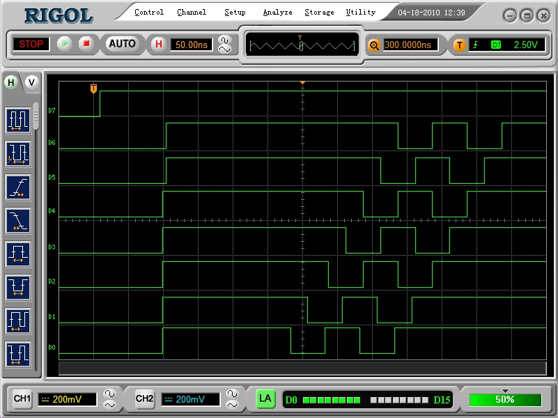
It seems answering forum posts makes you think a bit about things. I have never really looked into what the hub control logic actually does so as part of my investigation I hooked up a logic analyzer and wrote some code. All this does is start up 7 cogs with identical PASM software but each with a different I/O pin for outputting test pulses. I then wait to make sure they are all loaded and send out a trigger pulse. Each one responds in unison in 7 cycles from detecting the trigger and then I get each one to perform a dummy hub operation then output some more pulses. As you can see from hub_ack.png it is nice and regular synchronization of each cog to the hub as you would expect within the 200ns @80MHz window (16 cycles).
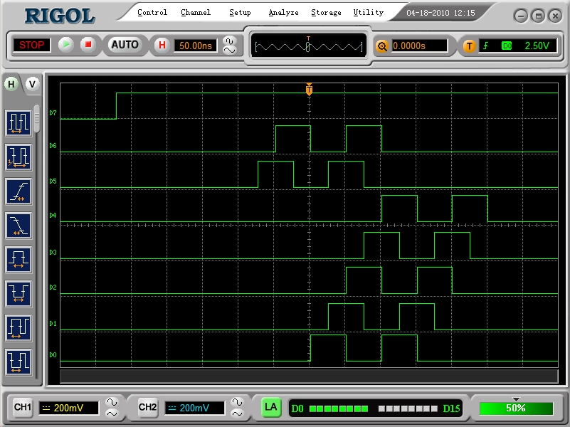
Now if I leave out the line marked ":ack" then you get what you see in hub_noack.png where cog 1 (D0) just misses out synchronizing to the hub due to the fact that it was the SPIN cog which is cog 0 which supplied the trigger pulse.
What I can see from the ACK pulses (the first low to high output) is that the cog takes 7 cycles to execute one instruction after a waitp and update the pin. It's pretty hard to examine what is actually going on this way when you don't have access to any internal timing signals but it's a learning exercise. Next steo might be to really hack it and delid the chip to STM it
Anyway, just thought I'd share what I am finding out, some of you probably know this already and maybe you would like to share what you have found.
▔▔▔▔▔▔▔▔▔▔▔▔▔▔▔▔▔▔▔▔▔▔▔▔
*Peter*
Now if I leave out the line marked ":ack" then you get what you see in hub_noack.png where cog 1 (D0) just misses out synchronizing to the hub due to the fact that it was the SPIN cog which is cog 0 which supplied the trigger pulse.
What I can see from the ACK pulses (the first low to high output) is that the cog takes 7 cycles to execute one instruction after a waitp and update the pin. It's pretty hard to examine what is actually going on this way when you don't have access to any internal timing signals but it's a learning exercise. Next steo might be to really hack it and delid the chip to STM it
Anyway, just thought I'd share what I am finding out, some of you probably know this already and maybe you would like to share what you have found.
' Hub operations tests
' 2010 Peter Jakacki

' This test will fire up the other 7 cogs with the same function
' which automatically selects a corresponding I/O pin P0..P6
' After all the cogs are loaded then the SPIN cog (0) will trigger them
' via P7 after which they will synch to the hub before outputing test pulses

' P0..7 are connected to a logic analyser

con

  _CLKMODE = XTAL1 + PLL16X
  _XINFREQ = 5_000_000
  clockfreq = ((_CLKMODE - XTAL1) >> 6) * _XINFREQ
  _1mS  = clockfreq /     1_000 'Divisor for  1 mS


pub main | i
  dira[noparse][[/noparse]7]~~
  outa[noparse][[/noparse]7]~
  repeat i from 0 to 6
    cognew(@entry,i<<2)
  ms(200)
  outa[noparse][[/noparse]7]~~                     ' synch test cogs from this I/O
  outa[noparse][[/noparse]7]~

pub ms(Period)                                    '1 mS
  if period
    waitcnt(_1mS * Period + cnt)


dat
        org   0
entry
              mov       outa,#0
              mov       r0,par
              shr       r0,#2
              mov       outpin,#1
              shl       outpin,r0
              mov       dira,outpin
              waitpeq   synch,synch
:ack          xor       outa,outpin             ' toggle output to show reaction time + instr execution
              rdlong    r0,#0                   ' dummy hub operation to test hub synch
:loop
              xor       outa,outpin             ' output test pulses
              xor       outa,outpin
              xor       outa,outpin
              xor       outa,outpin
:loop1
              jmp       #:loop1                 ' stop pulsing and let the I/O idle

synch         long %1000_0000
r0            res 1
outpin        res 1
▔▔▔▔▔▔▔▔▔▔▔▔▔▔▔▔▔▔▔▔▔▔▔▔
*Peter*
801 x 600 - 265K
801 x 600 - 260K
Comments
▔▔▔▔▔▔▔▔▔▔▔▔▔▔▔▔▔▔▔▔▔▔▔▔
Links to other interesting threads:
· Home of the MultiBladeProps: TriBlade,·RamBlade,·SixBlade, website
· Single Board Computer:·3 Propeller ICs·and a·TriBladeProp board (ZiCog Z80 Emulator)
· Prop Tools under Development or Completed (Index)
· Emulators: CPUs Z80 etc; Micros Altair etc;· Terminals·VT100 etc; (Index) ZiCog (Z80) , MoCog (6809)·
· Prop OS: SphinxOS·, PropDos , PropCmd··· Search the Propeller forums·(uses advanced Google search)
My cruising website is: ·www.bluemagic.biz·· MultiBlade Props: www.cluso.bluemagic.biz
▔▔▔▔▔▔▔▔▔▔▔▔▔▔▔▔▔▔▔▔▔▔▔▔
*Peter*
From the first image you can see that there are 15 cycles (D0) passing between the cog announcing release from waitpxx and it starting to toggle the pin. That leaves 11 cycles for the rdlong which in turn means cog 1 has to wait 3 cycles for its hub window. Cog 0 would have to wait 1 (but doesn't do anything). Cogs 6 and 7 are at -3 and -1, i.e. too late anyway. Then you remove a 4 cycle instruction which effectively moves cog 6 to a 1 wait cycle, cog 7 to 3 cycles after that, cog 0 (off sick) followed by cog 1.
Edit: Corrected cycle numbers (initial post was based on the images which are a bit hard to read). Current numbers are directly from silicon.
Post Edited (kuroneko) : 4/18/2010 8:57:06 AM GMT
▔▔▔▔▔▔▔▔▔▔▔▔▔▔▔▔▔▔▔▔▔▔▔▔
May the road rise to meet you; may the sun shine on your back.
May you create something useful, even if it's just a hack.
IdSD-LeR        waitpxx value, mask
      IdSDeR    xor outa, pmsk
    |------|
For the sake of clarity waitpxx is shown in it's best case timing (6 cycles). The inputs (result of 3rd cycle, D+1) are sampled first time during what I call Latch phase. Then 2 cycles pass to refetch the next instruction and the pin is toggled as a result of R (1/2 + 6 + 1/2).
@Steve: I find that a bit hard to swallow [noparse]:)[/noparse] A manual loop only samples once every 8 cycles while a waitpxx - once primed - samples every cycle. Then again, if it does the job I'm not going to argue.
Post Edited (kuroneko) : 4/19/2010 11:21:16 AM GMT
How many cycles does waitpxx take to detect the event immediately after another hub instruction?
▔▔▔▔▔▔▔▔▔▔▔▔▔▔▔▔▔▔▔▔▔▔▔▔
May the road rise to meet you; may the sun shine on your back.
May you create something useful, even if it's just a hack.
Anyway, the manual loop always seemed to work out better for me for low latency event detection/handling and timeouts.
▔▔▔▔▔▔▔▔▔▔▔▔▔▔▔▔▔▔▔▔▔▔▔▔
May the road rise to meet you; may the sun shine on your back.
May you create something useful, even if it's just a hack.
T0 SOURCE
T1 DESTINATION
T2 EXECUTE + INSTRUCTION FETCH (next instruction)
T3 RESULT + DECODE
Or is it fetch Destination first as DeSilva mentions (hey, I just read his document. About time!)
I suppose it doesn't really matter but the port read/write is probably more important to me. I know I could just keep on investigating but I just like to discuss these things as I come across them, so as not to miss any of the finer points.
I want to have a better understanding of what I see on the logic analyzer especially when my code reads or writes an I/O. I can see from some of my observations that after an output pin changes state that I have less than a 5ns window for the next instruction to sample an input. This is running the Prop at 80MHz. It would seem that it is not until the execute phase T2 that the input pin would be sampled which means that a port write must be taking 2 microcycles (fetch Source, fetch Destination) to update the pin after T3. It doesn't sound right. Setup and hold times should be in the order of a few ns I expect.
In the timing capture the top trace D2 is the asynchronous input while D1 is the updated output from the input and D0 is the reference clock. D2 is at the extreme of being sampled and can miss out even if it is synchronous with the reference at times but this could also be due to measurement errors and levels.
loop          xor       outa,#1                 ' reference - toggle P0
              test      inmask, ina wc          ' sample input
              muxc      outa,#2                 ' update output
              jmp       #loop
From my earlier examination of hub operations I was still curious as to whether the cog or the hub takes over. It seems to me that the hub has a lot more going on in it as there has to be the mechanism at reset to do a preset coginit of cog 0 (along with the scrambling), something that I would imagine being a part of the hub as otherwise cog 0 would have to be different from the other cogs. The datasheet confirms that this is the equivalent of a coginit as the loading of booter code into cog 0 takes approximately 496 times 16 cycles of around 12MHz (RCFAST).
▔▔▔▔▔▔▔▔▔▔▔▔▔▔▔▔▔▔▔▔▔▔▔▔
*Peter*
IdSDeR -----------------Cog RAM------------------ State R/W Address Data In Data Out Other --------------------------------------------------------------------------------------- 0 R source - - - 1 R destination - source S register is latched 2 R instruction - destination Final S is mux'd and latched, D register is latched 3 W destination result instruction ALU settles with S/D inputs, result is written to D registerina, phsx and cnt are special in that they are sampled during e. Outputs are always written during R.
http://forums.parallax.com/showthread.php?p=861676
http://forums.parallax.com/showthread.php?p=864343
coginit timing
Cog L(auncher) starts cog T(arget), time taken is:
The first 8 cycles belong to the actual coginit instruction (not counting 0..15 sync), followed by 511*16+8 to upload 512 longs from hub to cog RAM. Then there are 4 cycles unaccounted for which I believe cover the last steps of initialisation (e.g. PC, flags, doesn't really matter). A is simply the resulting slot offset for a given cog pair within the hub window, e.g. starting cog 4 from cog 0 is faster than starting cog 3. After all that the cog starts executing the first instruction which is -4 before its first hub window.
Post Edited (kuroneko) : 4/19/2010 9:46:58 AM GMT
IIRC the sampling of the INA occurs in the e cycle which is in a single loop when it is reached in the waitpxx instruction.
We know that a waitpxx takes a minimum of 6 cycles (IIRC this has been agreed and is not 5+ as per the manual).
Here is my speculation from my recollection etc...
IdSD (4 cycles) of waitpxx have been executed and the waitpxxx tests the pin in the 5th cycle (the e cycle). When the waitpxx instruction finally agrees (during the e cycle where the input pin is correct) the instruction continues with the R cycle. I believe because of the wait in the e loop, the pipeline gets flushed and so we have a 2 cycle hit, because the next Id cycles are performed again after the R cycle. Most likely this is to reduce power usage from continually fetching the I of the next instruction during the extended e cycle(s).
There was another thread where Chip answered some internal pin timing delays.
As for the cog loading... It must be done using the round-robbin approach as it does not interfere with existing cogs getting hub access and it's load time is fixed (determinate) according to what I understand Chip has said. PropII will still only load longs, not quad longs, but we can load multiple quad longs by·an instruction - yes 1 instruction·(for overlays, etc).
▔▔▔▔▔▔▔▔▔▔▔▔▔▔▔▔▔▔▔▔▔▔▔▔
Links to other interesting threads:
· Home of the MultiBladeProps: TriBlade,·RamBlade,·SixBlade, website
· Single Board Computer:·3 Propeller ICs·and a·TriBladeProp board (ZiCog Z80 Emulator)
· Prop Tools under Development or Completed (Index)
· Emulators: CPUs Z80 etc; Micros Altair etc;· Terminals·VT100 etc; (Index) ZiCog (Z80) , MoCog (6809)·
· Prop OS: SphinxOS·, PropDos , PropCmd··· Search the Propeller forums·(uses advanced Google search)
My cruising website is: ·www.bluemagic.biz·· MultiBlade Props: www.cluso.bluemagic.biz
http://forums.parallax.com/showthread.php?p=861676
http://forums.parallax.com/showthread.php?p=860477
▔▔▔▔▔▔▔▔▔▔▔▔▔▔▔▔▔▔▔▔▔▔▔▔
Links to other interesting threads:
· Home of the MultiBladeProps: TriBlade,·RamBlade,·SixBlade, website
· Single Board Computer:·3 Propeller ICs·and a·TriBladeProp board (ZiCog Z80 Emulator)
· Prop Tools under Development or Completed (Index)
· Emulators: CPUs Z80 etc; Micros Altair etc;· Terminals·VT100 etc; (Index) ZiCog (Z80) , MoCog (6809)·
· Prop OS: SphinxOS·, PropDos , PropCmd··· Search the Propeller forums·(uses advanced Google search)
My cruising website is: ·www.bluemagic.biz·· MultiBlade Props: www.cluso.bluemagic.biz
Yes, the coginit is still performed round-robin with one long per access which agrees with the boot load time and my measurements but I was actually just a little curious about the architecture of the hub itself <scratch these musings for now>.
▔▔▔▔▔▔▔▔▔▔▔▔▔▔▔▔▔▔▔▔▔▔▔▔
*Peter*
OK, but how does that compare with what Chip was saying about INA and also Ray in an old post when he said:
"The pins are PHYSICALLY sampled near the end of the "S" cycle due to the internal gate delays before latching takes place at the start of the "D" (or end of the "S") cycle."
I'm checking and asking also because there seems to be some confusion or at least lack of agreement in this regard. Is there an updated timing diagram available?
▔▔▔▔▔▔▔▔▔▔▔▔▔▔▔▔▔▔▔▔▔▔▔▔
*Peter*
So, at the start of D (i.e. the end of S) the source register is latched into the S-Latch. At the start of e (i.e. the end of D) the destination register is latched into the D-Latch. In at the start of e (i.e. the end of D) the input pins (this can also be PHSx, CNT, etc depending on the instruction) are also latched into the IN-latch. Now, depending on the instruction, the multiplexer either routes the S-Latch or the IN-Latch to the ALU, as well as the D-Latch. e then executes the ALU cycle to perform the bittest.
Does this make sense?
▔▔▔▔▔▔▔▔▔▔▔▔▔▔▔▔▔▔▔▔▔▔▔▔
Links to other interesting threads:
· Home of the MultiBladeProps: TriBlade,·RamBlade,·SixBlade, website
· Single Board Computer:·3 Propeller ICs·and a·TriBladeProp board (ZiCog Z80 Emulator)
· Prop Tools under Development or Completed (Index)
· Emulators: CPUs Z80 etc; Micros Altair etc;· Terminals·VT100 etc; (Index) ZiCog (Z80) , MoCog (6809)·
· Prop OS: SphinxOS·, PropDos , PropCmd··· Search the Propeller forums·(uses advanced Google search)
My cruising website is: ·www.bluemagic.biz·· MultiBlade Props: www.cluso.bluemagic.biz
http://forums.parallax.com/showthread.php?p=862211
As for updated timing diagrams, I think Ray intended to do that ...
The pins are PHYSICALLY sampled at the start of e (or end of D = same thing), but because of internal gate delays, it is ACTUALLY about ~2.5ns before e.
An output is PHYSICALLY written at the start of R (or end of e = same thing), but because of internal gate delays, it is ACTUALLY about ~2.5ns after e.
This means that the INPUT is sampled 3 clocks after an OUTPUT less two lots of gate delays = 37.5ns - ~2.5ns - ~2.5ns = ~33ns for
mov outa,xxxx
mov xxx,ina
When "mov xxx,ina" is replaced with a "waitpxx mask,ina" instruction there are an extra 2 clocks in there somewhere. I think they are after the sampling but this is unconfirmed and maybe due to pipeline reload.
▔▔▔▔▔▔▔▔▔▔▔▔▔▔▔▔▔▔▔▔▔▔▔▔
Links to other interesting threads:
· Home of the MultiBladeProps: TriBlade,·RamBlade,·SixBlade, website
· Single Board Computer:·3 Propeller ICs·and a·TriBladeProp board (ZiCog Z80 Emulator)
· Prop Tools under Development or Completed (Index)
· Emulators: CPUs Z80 etc; Micros Altair etc;· Terminals·VT100 etc; (Index) ZiCog (Z80) , MoCog (6809)·
· Prop OS: SphinxOS·, PropDos , PropCmd··· Search the Propeller forums·(uses advanced Google search)
My cruising website is: ·www.bluemagic.biz·· MultiBlade Props: www.cluso.bluemagic.biz
The input to output timing is relevant to me as I was doing some high-speed serial timing and I needed to know where the input was actually being sampled in relation to the diagnostic output pin states.
▔▔▔▔▔▔▔▔▔▔▔▔▔▔▔▔▔▔▔▔▔▔▔▔
*Peter*
So yes, from a mov xxx,ina to mov outa,xxx should be ~62.5 + ~2.5 + ~2.5 = ~67.5ns
However, from a waitpxx to mov out,xxx I think will be ~67.5ns + 25ns = ~92.5ns
▔▔▔▔▔▔▔▔▔▔▔▔▔▔▔▔▔▔▔▔▔▔▔▔
Links to other interesting threads:
· Home of the MultiBladeProps: TriBlade,·RamBlade,·SixBlade, website
· Single Board Computer:·3 Propeller ICs·and a·TriBladeProp board (ZiCog Z80 Emulator)
· Prop Tools under Development or Completed (Index)
· Emulators: CPUs Z80 etc; Micros Altair etc;· Terminals·VT100 etc; (Index) ZiCog (Z80) , MoCog (6809)·
· Prop OS: SphinxOS·, PropDos , PropCmd··· Search the Propeller forums·(uses advanced Google search)
My cruising website is: ·www.bluemagic.biz·· MultiBlade Props: www.cluso.bluemagic.biz
- setup a duty cycle counter in a way that a test mask, ina wz catches the pulse (nz).
- replace the test with e.g. a waitpeq mask, mask
We know that for a move instruction ina is sampled in the execute phase. If the same is true for waitpxx then the replacement should result in the minimum 6 cycle timing for waitpeq. It doesn't ...BTW: the mov xxx,ina is latched at the commencement of the e phase but it latches what was there ~2.5ns earlier (i.e. ~2.5ns before the end of the D phase) and we know the e phase repeats if not satisfied.
▔▔▔▔▔▔▔▔▔▔▔▔▔▔▔▔▔▔▔▔▔▔▔▔
Links to other interesting threads:
· Home of the MultiBladeProps: TriBlade,·RamBlade,·SixBlade, website
· Single Board Computer:·3 Propeller ICs·and a·TriBladeProp board (ZiCog Z80 Emulator)
· Prop Tools under Development or Completed (Index)
· Emulators: CPUs Z80 etc; Micros Altair etc;· Terminals·VT100 etc; (Index) ZiCog (Z80) , MoCog (6809)·
· Prop OS: SphinxOS·, PropDos , PropCmd··· Search the Propeller forums·(uses advanced Google search)
My cruising website is: ·www.bluemagic.biz·· MultiBlade Props: www.cluso.bluemagic.biz
▔▔▔▔▔▔▔▔▔▔▔▔▔▔▔▔▔▔▔▔▔▔▔▔
*Peter*
IdSD-LeR
      IdSDeR
Labelling is subjective, so no point arguing [noparse];)[/noparse] Above timing is minimal (6). I see it as a normal instruction which has 2 extra cycles inserted. One could argue that everything between D and R is some variation of e but as I said, it's subjective. Cycle 5 ("-") does indeed latch our special friends (ina, phsx, cnt in source slot) but only to have them ready as a static mask during comparison (it's a shame really that you can't have live masks). Cycle 6 ("L") is the first looking at ina and is repeated as long as the condition isn't met. Once it is the instruction finishes with eR interleaved with the next instruction's Id.
I have proof (as far as observation by s/w goes) for -LR, and the location for execute makes most sense just before Ra because the ALU is in heavy use during L which means that any result would have to be calculated after that to be ready for R.
a if used with wr the instruction performs value += mask [noparse][[/noparse]+1] - the +1 for waitpne only - most likely due to their close relationship to waitcnt
(replace this text with your code)

start of e clock                                    start of repeated e clock                        start of R clock
v                                                   v                                                v
|-------------------------|                         |----------------------|                         |--------------
|                         |                         |                      |                         |
|                         |-------------------------|                      |-------------------------|

^                                                   ^ina is latched here                                 ina is latched here
(what was on the pins ~2.5ns earlier)               (what was on the pins ~2.5ns earlier)

                   ^^^^^^^^^^^^^^^^^^^^^^^^^^^^^^^                     ^^^^^^^^^^^^^^^^^^^^^^^^^^^^^

                   somewhere along here the ALU                        somewhere along here the ALU
                   determines that the condition                       determines that the condition
                   IS NOT met                                          IS met
If the condition is met before the waitpxx samples the pin (including setup time), then why does it take 6 clocks to execute and where are those extra 2 clock inserted ? Or, am I wrong and waitpxx does not take 6 clock minimum ?
What do you think?
▔▔▔▔▔▔▔▔▔▔▔▔▔▔▔▔▔▔▔▔▔▔▔▔
Links to other interesting threads:
· Home of the MultiBladeProps: TriBlade,·RamBlade,·SixBlade, website
· Single Board Computer:·3 Propeller ICs·and a·TriBladeProp board (ZiCog Z80 Emulator)
· Prop Tools under Development or Completed (Index)
· Emulators: CPUs Z80 etc; Micros Altair etc;· Terminals·VT100 etc; (Index) ZiCog (Z80) , MoCog (6809)·
· Prop OS: SphinxOS·, PropDos , PropCmd··· Search the Propeller forums·(uses advanced Google search)
My cruising website is: ·www.bluemagic.biz·· MultiBlade Props: www.cluso.bluemagic.biz
As for the sample code, it's written for the demo board and setup so that a test eins, ina wz catches a duty pulse. This is indicated by LED 16 being lit. LEDs 17..23 show the cycle time for the observed instruction (4 for a test). Swapping this with the waitpeq will result in a 13 cycle display (missed condition -> 6 + 8 - 1). Adjusting phsa to issue the pulse one cycle later (%00100_0000) will result in 6 consumed cycles, two cycles later (%00000_0000) in 7 consumed cycles.
{
       mov temp, phsa

       |    S    |    D    |    E    |    R    |
  +----+    +----+    +----+    +----+    +----+    +----+    +----+    +----+    +----+    +----+
  |    |    |    |    |    |    |    |    |    |    |    |    |    |    |    |    |    |    |    |
--+    +----+    +----+    +----+    +----+    +----+    +----+    +----+    +----+    +----+    +--
            ^         ^         ^
            |         |         |
       N*frqa         |         phsa is sampled and stored into temp, (N+1)*frqa
                      |         ^
             (N+1)*frqa         |
                                (N+2)*frqa

       test temp, ina wz

       |    S    |    D    |    E    |    R    |
  +----+    +----+    +----+    +----+    +----+    +----+    +----+    +----+    +----+    +----+
  |    |    |    |    |    |    |    |    |    |    |    |    |    |    |    |    |    |    |    |
--+    +----+    +----+    +----+    +----+    +----+    +----+    +----+    +----+    +----+    +--
                       +---------+
            duty pulse |        ^|
-----------------------+        |+------------------------------------------------------------------
                                |
                                ina is sampled and used for flag update (duty pulse is "seen")


       waitpeq outa, phsa wr '(6)

       |    S    |    D    |   e/2   |    L    |    e    |    R    |
  +----+    +----+    +----+    +----+    +----+    +----+    +----+    +----+    +----+    +----+
  |    |    |    |    |    |    |    |    |    |    |    |    |    |    |    |    |    |    |    |
--+    +----+    +----+    +----+    +----+    +----+    +----+    +----+    +----+    +----+    +--
                                ^         ^         ^         ^
                                |         |         |         |
  phsa is sampled and latched for         |         |         |
  ALU operation (value ? ina & mask)      |         |         |
                                          ina is sampled, ANDed with mask (== latched phsa)
                                          and compared with value -> equal
                                                    |         |
                               calculate outa += phsa         results are updated, observable by
                                                              using wr and outa in the dst slot

 I call it e/2 for now because part of the normal execute cycle still happens, e.g. final latching.
 Real ina sampling (for comparison) IS NOT done here, consider this

       mov     mask, #1
       waitpeq mask, mask '(6)

       |    S    |    D    |   e/2   |    L    |    e    |    R    |
  +----+    +----+    +----+    +----+    +----+    +----+    +----+    +----+    +----+    +----+
  |    |    |    |    |    |    |    |    |    |    |    |    |    |    |    |    |    |    |    |
--+    +----+    +----+    +----+    +----+    +----+    +----+    +----+    +----+    +----+    +--

                                 +---------+
                      duty pulse |         |
---------------------------------+         +--------------------------------------------------------

This waitpeq will take 6 cycles only if the duty pulse is placed like this (to be read during L).
Placing it one cycle earlier like for the mov above will make it last 6 + (duty period - 1) which
means that it can't have been sampled during e/2.

       mov     mask, #1
       waitpeq mask, mask '(7)

       |    S    |    D    |   e/2   |    L    |    L    |    e    |    R    |
  +----+    +----+    +----+    +----+    +----+    +----+    +----+    +----+    +----+    +----+
  |    |    |    |    |    |    |    |    |    |    |    |    |    |    |    |    |    |    |    |
--+    +----+    +----+    +----+    +----+    +----+    +----+    +----+    +----+    +----+    +--

                                           +---------+
                                duty pulse |         |
-------------------------------------------+         +----------------------------------------------

}
As for the insertion, what I meant was something like this (sorry, got carried away):
Post Edited (kuroneko) : 4/20/2010 4:53:37 AM GMT
According to Chip, each phase begins on the rising clock edge, so your clock divisions should be 1/2 clock later. Also, the e phase is repeated in a loop until the condition is met.
I will look and try your code later - other things I must do first unfortunately.
▔▔▔▔▔▔▔▔▔▔▔▔▔▔▔▔▔▔▔▔▔▔▔▔
Links to other interesting threads:
· Home of the MultiBladeProps: TriBlade,·RamBlade,·SixBlade, website
· Single Board Computer:·3 Propeller ICs·and a·TriBladeProp board (ZiCog Z80 Emulator)
· Prop Tools under Development or Completed (Index)
· Emulators: CPUs Z80 etc; Micros Altair etc;· Terminals·VT100 etc; (Index) ZiCog (Z80) , MoCog (6809)·
· Prop OS: SphinxOS·, PropDos , PropCmd··· Search the Propeller forums·(uses advanced Google search)
My cruising website is: ·www.bluemagic.biz·· MultiBlade Props: www.cluso.bluemagic.biz
I don't think it really matters. This way it's easier to read for me, the active edge is preceded by data setup and followed by output propagation.
Yes, so? I repeat the L phase (until the condition is met) as indicated in the last diagram. My point is simply that the cycle following D and the one preceding R have nothing to do with pin monitoring.
Chip calls your "L" phase the "e" phase (the one between D and R) and the phase begins at the rising edge of the clock pulse. I changed my diagrams to reflect that. Sorry to be pedantic. I don't agree with your statement (semantics only) since when this "e" phase repeats it actually is sampling the source pins 2.5ns before the rising edge of the start of the "e" phase, so this means as it repeats it samples 2.5ns from the end of the "e" phase for the next "e" phase but it only latches if the condition was not met (i.e. repeats). The whole "e" phase is actually the ALU phase where the comparison is physically done and the answer to that is available near the end of the "e" phase ready for the transition of "e" to "R" or back to "e" again.
Maybe it is just easier to say that the pins are latched at the start of "e" (rising edge of clock) and "e" does the compare. Then say there is a sampling·setup time of ~2.5ns prior to latching.
Have you worked out where the extra 2 clocks fit in with the waitpxx? Is it after the sampling before the next instruction (i.e. a pilepline reload or equivalent)? I am not happy with the 3 waitpxx diagrams. I will try later to see what I can verify.
This is great to thoroughly understand so I hope you are not offended by my comments.
▔▔▔▔▔▔▔▔▔▔▔▔▔▔▔▔▔▔▔▔▔▔▔▔
Links to other interesting threads:
· Home of the MultiBladeProps: TriBlade,·RamBlade,·SixBlade, website
· Single Board Computer:·3 Propeller ICs·and a·TriBladeProp board (ZiCog Z80 Emulator)
· Prop Tools under Development or Completed (Index)
· Emulators: CPUs Z80 etc; Micros Altair etc;· Terminals·VT100 etc; (Index) ZiCog (Z80) , MoCog (6809)·
· Prop OS: SphinxOS·, PropDos , PropCmd··· Search the Propeller forums·(uses advanced Google search)
My cruising website is: ·www.bluemagic.biz·· MultiBlade Props: www.cluso.bluemagic.biz
What two extra clocks are you referring to? You have IdSD then a half baked e (latch source value only, i.e. cnt, phsx, ina) then any number of L (1..N) followed by eR. Which is all shown in the diagram(s). So excluding the initial Id I count 6+N, all accounted for.
I'm at a loss really. I have the code here in front of me which tells me that the funtionality is like I outlined above. What does it take to convince you? I suggest you go through the test code for the sample pulse location and then we can continue the discussion [noparse]:)[/noparse]
BTW: I know there is a 2.5ns setup time, but that's not relevant for explaining the HowTo.