

My first time designing a circuit and circuit board.
 Jimbo30
Posts: 129
Jimbo30
Posts: 129
Below are a couple pictures of the circuit I will be using for my project.· BS2p-40, MAX485 IC, two ADC0831, reed relay and some other stuff.· I must say it was a challenge and learning experience all at the same time.· The only issue I ran into was the H-bridge circuits I bought only allow 2-amps per channel so I had to order better h-bridge boards that can handle more amps.
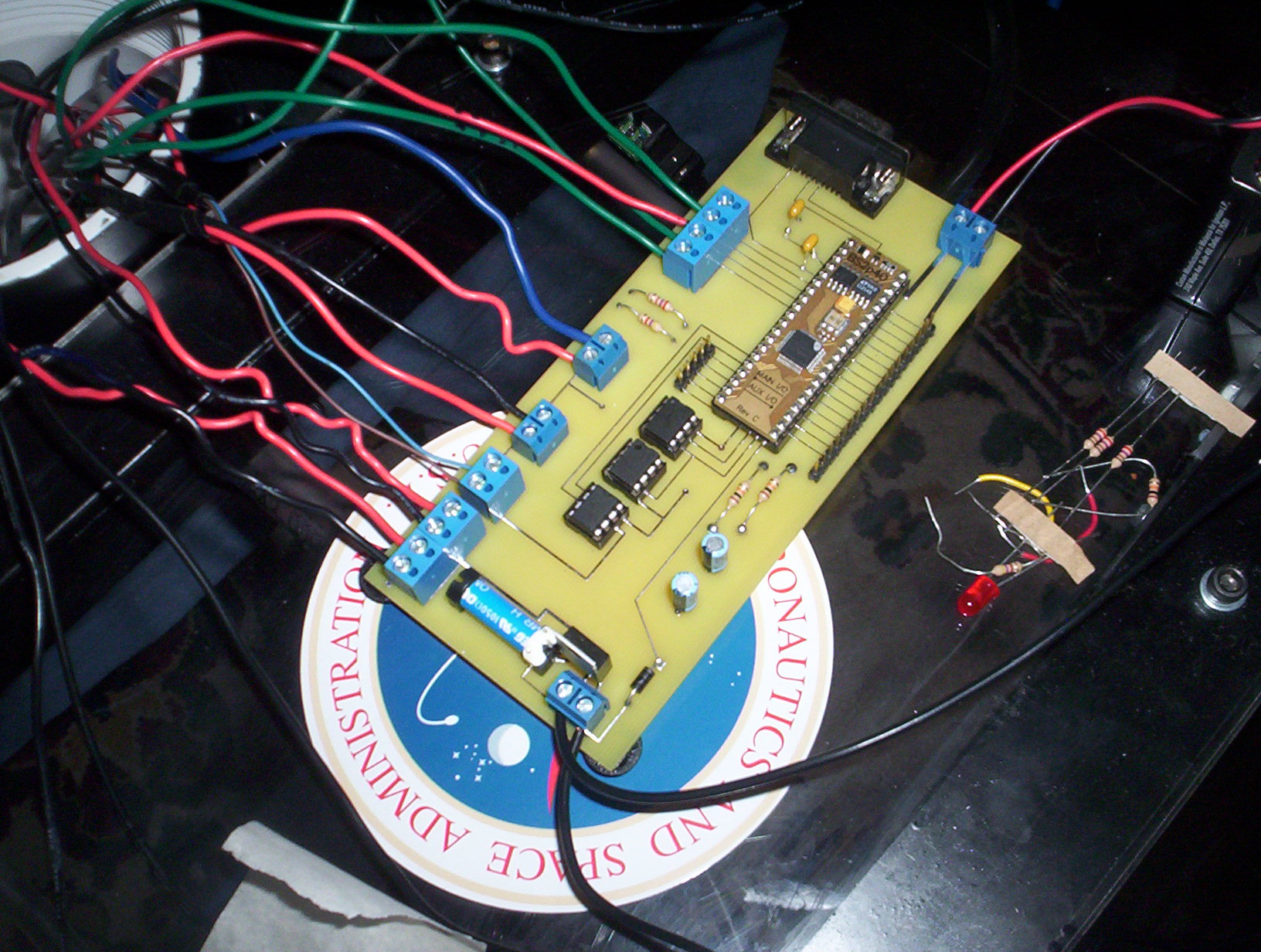
1632 x 1232 - 464K
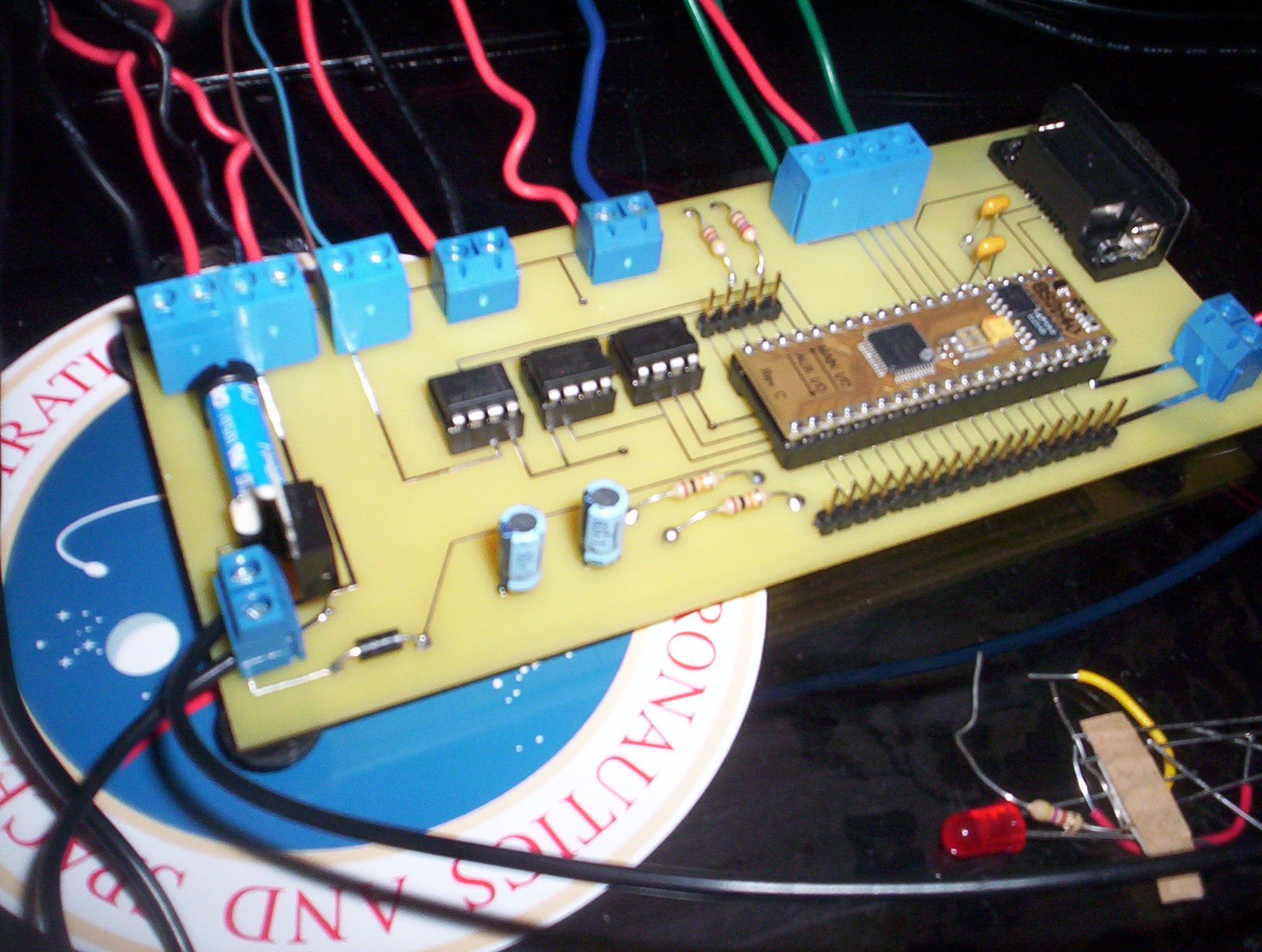
1632 x 1232 - 413K
Comments
How're you using all this then?
I was going to try etching it at the Tech college I went to, but I figured there would be less headaches if I just used a PCB design software and have the board manufactured. As for it being uncluttered, I was nervous when designing it, lol. This board is the control system for the ROV I am building. The only thing I have left to do is the motor control. I have the motors communicating, but my H-bridge boards go into thermal overload after a few minutes of operation. I am new to robot building so it is a learning experience as I go.
Post Edited (Jimbo30) : 4/16/2010 4:23:19 AM GMT
Very nice job, good layout. Things where they should be. Nice job making your leftover I/O pins accessible. I think that should always be done for any design.
▔▔▔▔▔▔▔▔▔▔▔▔▔▔▔▔▔▔▔▔▔▔▔▔
Andrew Williams
WBA Consulting
WBA-TH1M Sensirion SHT11 Module
Special Olympics Polar Bear Plunge, Mar 20, 2010
▔▔▔▔▔▔▔▔▔▔▔▔▔▔▔▔▔▔▔▔▔▔▔▔
Leon Heller
Amateur radio callsign: G1HSM
Post Edited (Leon) : 4/16/2010 9:22:15 PM GMT
oh,... [noparse]:)[/noparse]
Do you have a diode across the relay coil?
▔▔▔▔▔▔▔▔▔▔▔▔▔▔▔▔▔▔▔▔▔▔▔▔
Leon Heller
Amateur radio callsign: G1HSM
On my PWM channels, I am now stuck on trying to get the right combination of a resistor and capacitor for charge time so I can·set the speed of my motor correctly.··What seems to work well for one motor doesn't necessarily work for another motor· ·.··· I used a small 5V motor (without a load)·for testing and now that I am trying to get the 12V motor with a muffin fan on it everything is quite different due to the load I have on the motor.· I like the challenge though!· Do you have any suggestions??????