

Solved! Propeller Robot Control Board browning out
 vanmunch
Posts: 568
vanmunch
Posts: 568
***********
Update 4-16-10
***********
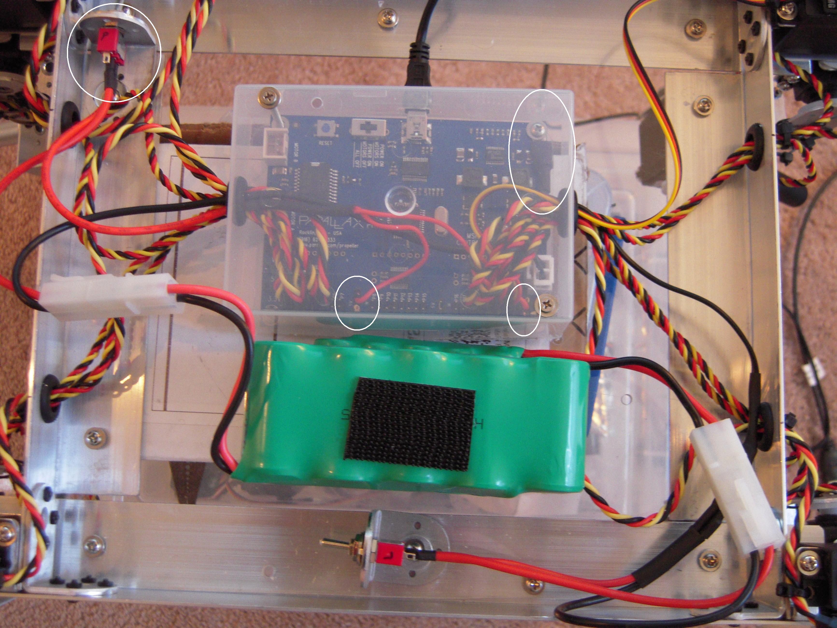
Following the great ideas of everyone, we were able to come up with a way to add a second power supply to the Propeller Robot Control Board by removing the jumpers and supplying power directly to the center pins and connecting the ground to one of the four screw holes. I've attached a picture showing the mod. The picture shows the two power supply switches marked "P" (power) and "L" logic. The logic's smaller battery pack is obscured by the larger, power battery pack. I hope this helps someone else out, but please read on to fully understand everything before you try it yourself.
**********
Original
**********
Hello,
I am having a problem with getting more than a few servos working at the same time (i.e. holding their position). I'm able to control 3-4 servos before the servos just twitch once and go still. I've figured out that the servos are causing the circuit to brown out . It looks like the entire board shares the same power supply or is it possible to power the prop with a separate power supply through the barrel jack? The documentation makes it sound like it would just make it the single power supply resulting in the same problem. Anyhow, any suggestions would be great otherwise I'll have to figure out how to, sniff... return the board.... sniff... sniff... [noparse]:([/noparse]
Dave
Just in case it's something else:
I'm using the Servo32v7 object with the Propeller Robot Control Board to control a new quad walker that I'm making. The top object's code is below.
{{
Quad_walker_V1.spin
}}
CON
_clkmode = xtal1 + pll16x
_xinfreq = 5_000_000
RFHip = 0
RFKnee = 1
RFFoot = 2
RRHip = 21
RRKnee = 22
RRFoot = 23
LRHip = 18
LRKnee = 19
LRFoot = 20
LFHip = 3
LFKnee = 4
LFFoot = 5
OBJ
SERVO : "Servo32v7.spin"
Debug : "FullDuplexSerialPlus"
PUB Quad_Walking_Servo32_DEMO | temp
Debug.start(31, 30, 0, 57600)
waitcnt(clkfreq*3 + cnt)
Debug.Str(String("Am I browning out????"))
SERVO.Start 'Start Servo handler
SERVO.Set(RFHip, 1500) 'Move Servo to Center
SERVO.Set(RFKnee,1500)
SERVO.Set(RFFoot,1500)
SERVO.Set(RRHip, 1500)
' SERVO.Set(RRknee,1500)
' SERVO.Set(RRFoot,1500)
' SERVO.Set(LRHip, 1500)
' SERVO.Set(LRKnee,1500)
' SERVO.Set(LRFoot,1500)
' SERVO.Set(LFHip, 1500)
' SERVO.Set(LFKnee,1500)
' SERVO.Set(LFFoot,1500)
repeat 1500000
▔▔▔▔▔▔▔▔▔▔▔▔▔▔▔▔▔▔▔▔▔▔▔▔
My wife is very, very understanding
Post Edited (vanmunch) : 4/16/2010 11:23:16 PM GMT
Update 4-16-10
***********
Following the great ideas of everyone, we were able to come up with a way to add a second power supply to the Propeller Robot Control Board by removing the jumpers and supplying power directly to the center pins and connecting the ground to one of the four screw holes. I've attached a picture showing the mod. The picture shows the two power supply switches marked "P" (power) and "L" logic. The logic's smaller battery pack is obscured by the larger, power battery pack. I hope this helps someone else out, but please read on to fully understand everything before you try it yourself.
**********
Original
**********
Hello,
I am having a problem with getting more than a few servos working at the same time (i.e. holding their position). I'm able to control 3-4 servos before the servos just twitch once and go still. I've figured out that the servos are causing the circuit to brown out . It looks like the entire board shares the same power supply or is it possible to power the prop with a separate power supply through the barrel jack? The documentation makes it sound like it would just make it the single power supply resulting in the same problem. Anyhow, any suggestions would be great otherwise I'll have to figure out how to, sniff... return the board.... sniff... sniff... [noparse]:([/noparse]
Dave
Just in case it's something else:
I'm using the Servo32v7 object with the Propeller Robot Control Board to control a new quad walker that I'm making. The top object's code is below.
{{
Quad_walker_V1.spin
}}
CON
_clkmode = xtal1 + pll16x
_xinfreq = 5_000_000
RFHip = 0
RFKnee = 1
RFFoot = 2
RRHip = 21
RRKnee = 22
RRFoot = 23
LRHip = 18
LRKnee = 19
LRFoot = 20
LFHip = 3
LFKnee = 4
LFFoot = 5
OBJ
SERVO : "Servo32v7.spin"
Debug : "FullDuplexSerialPlus"
PUB Quad_Walking_Servo32_DEMO | temp
Debug.start(31, 30, 0, 57600)
waitcnt(clkfreq*3 + cnt)
Debug.Str(String("Am I browning out????"))
SERVO.Start 'Start Servo handler
SERVO.Set(RFHip, 1500) 'Move Servo to Center
SERVO.Set(RFKnee,1500)
SERVO.Set(RFFoot,1500)
SERVO.Set(RRHip, 1500)
' SERVO.Set(RRknee,1500)
' SERVO.Set(RRFoot,1500)
' SERVO.Set(LRHip, 1500)
' SERVO.Set(LRKnee,1500)
' SERVO.Set(LRFoot,1500)
' SERVO.Set(LFHip, 1500)
' SERVO.Set(LFKnee,1500)
' SERVO.Set(LFFoot,1500)
repeat 1500000
▔▔▔▔▔▔▔▔▔▔▔▔▔▔▔▔▔▔▔▔▔▔▔▔
My wife is very, very understanding
Post Edited (vanmunch) : 4/16/2010 11:23:16 PM GMT
3466 x 2599 - 811K
Comments
As Jack Buffington point out, this could be a result of not using a separate power supply for the Servo's. Hobby servos are capable of drawing in excess of 1 Amp of current when moving from one location to another. Once they are at the desired position the current can drop to a few 100 mA.
I would tend to rule out the Servo32 program and recommend a separate power supply for the Servo's and see if that helps things out. If you are still having problems after that, let us know and perhaps we can suggest an alternate route to solve the problem.
▔▔▔▔▔▔▔▔▔▔▔▔▔▔▔▔▔▔▔▔▔▔▔▔
Beau Schwabe
IC Layout Engineer
Parallax, Inc.
Good news:
I switched the jumpers so that the servos were powered via the 6-15V VIN input (connected to a ~6.5V battery) and this has allowed the servos (12 Hitec Hs-645MG) to be powered without browning out the cirut each time (although it did do it once when I was severly stressing the servos). Before it would brownout when 3-4 servos were connected and it was just sitting there.
I completely agree that the Servo32 program wasn't causing the problem. I think it's great!
Bad news:
The problem appears that you can not connect two power supplies to the Propeller Robot Control Board like you can with the propeller servo controller. (I would prefer two power supplies) The Propeller Robot Control Board documentation mentions that the power supply is through the barrel OR the V6-15. I tested this by connecting ~6V to the barrel and ~6.5V to the 6-15V input. It acted like the board only took the power from the barrel. I tested it again by first applying power to the 6-15 input and then the barrel and no difference. I had hoped that the board worked by allowing you to supply power to the controller via the barrel and power the servos through the separate power supply (6-15V input).
Does anyone know for sure if you can connect two power supplies to the Propeller Robot Control Board? Maybe there's another jumper that I'm missing or something? Otherwise I'll have to see how often the whole thing brown's out when the servos are under stress (ie walking).
Anyhow, Thanks for all of the help. If the browning out becomes a problem (even with the VIN solution) I can always wire up something custom. I wish that I had tried the jumpers before posting, but hopefully this will help someone else out there. [noparse]:)[/noparse]
Dave
Ahhh, I understand...
"Using the Barrel Jack Connector disables the Battery Pack Socket." - so if you had a battery connected to the Battery Pack Socket [noparse][[/noparse]8] it would become disconnected if you were using the Barrel Jack Connector [noparse][[/noparse]9] for power.
"The input voltage (VIN) is also the motor voltage." - supplied from the Battery Pack Socket or Barrel Jack Connector also supplies Vin to the On-board 3.3V & 5V switching power supply, so you need at least 6.5V her to have enough voltage overhead.
"To the right of each group of I/O headers is a jumper that allows either 5V or VIN to be available at the center (power) pin of that group." - Which I assume you are moving to the VIN position, but that doesn't help much.
In order to have TWO power supplies, you almost need a third position on this header to select from ... 5V,VIN, and a third power source VAUX.
Hmmm.. for a temporary fix, omit the jumper that allows you to select 5V, or VIN, and try connecting the center pin to your "Second" power supply specifically for the servos (Should not exceed the voltage rating of the servo). This way Vccb on the level shifter is still 5V, but power to the servo is separate. Make sure that you still have a common ground between the two power supplies.
Note: If you have a spare servo connector the above operation would be a simple matter of plugging the spare connector into an unused servo bay and not connecting anything to the white signal wire, use the black and red to connect to your 'second' power supply. Make sure that you remove the jumper option for 5V or VIN operation first.
Reference:
Propeller Robot Control Board Manual
▔▔▔▔▔▔▔▔▔▔▔▔▔▔▔▔▔▔▔▔▔▔▔▔
Beau Schwabe
IC Layout Engineer
Parallax, Inc.
Post Edited (Beau Schwabe (Parallax)) : 4/13/2010 8:04:04 PM GMT
The only thing that I might add, is if you implement Beau's Aux power to the servo headers through the one or two pin configuration, you should pull all the 5V/VIN jumpers (all three banks).
Jim
"...Now Beau, get back to the Prop II!" - fair enough, but anytime there is an object I wrote that gets 'flagged' with a problem, I get notified, and try to resolve the issue in a timely manor. Otherwise the problem gets buried without a real solution.
▔▔▔▔▔▔▔▔▔▔▔▔▔▔▔▔▔▔▔▔▔▔▔▔
Beau Schwabe
IC Layout Engineer
Parallax, Inc.
I have been working on a daughter board that will automatically bypass the translator chip and provide a resister pack and servo headers to communicate with the Prop directly. I could add an option to put a battery connector on the board.
I don’t physically have the Propeller Robot Control Board in my hands to take the dimensions for my new board, but I’m hoping it is based on .100 spacing. I’ll be ordering a PRCB board this week to refine my design.
Jim
Jim
Thanks for everyone's help. I think I'll try and remove the jumpers on the two sets of eight pins that I'm using for the servos (I'm trying to reserve the center eight for sensor inputs) and plug the power directly into the red and black pins and make sure that everything shares the same ground. (Beau, you helped me out with this a couple of weeks ago where I found out the hard way) and on a side note:
"anytime there is an object I wrote that gets 'flagged' with a problem, I get notified, and try to resolve the issue in a timely manor."
I think you just taught me to add "servo32" any problem that I have in the future, servos, wifi, taxes... [noparse]:)[/noparse]
Anyhow, I'll let everyone know how the jumper thing works out and I've attached a couple of pictures of the quadruped that I'm building along with a couple of close-ups. I should have a couple of videos of it walking in awhile, unless something happens.
▔▔▔▔▔▔▔▔▔▔▔▔▔▔▔▔▔▔▔▔▔▔▔▔
My wife is very, very understanding