

BS2 - Wireless level data monitoring using the MURS frequency band
 Douglas M
Posts: 9
Douglas M
Posts: 9
Although there is nothing ground breaking here, I thought it would be an interesting project to share due to the use of four BS2 micro-controllers sharing data, remote wireless communications using the MURS frequency's and the Parallax REDi Web server in a practical application.
Project Description:
The goal of this project is to monitor level data located in a remote location that is not serviced by electric utilities or land line telephone.
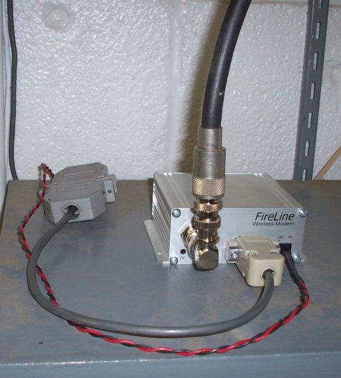
Remote monitoring is not new, and there are a number of commercial systems already available for this purpose. Most of these systems use cellular, or radio transceivers using the 900 megahertz or the gigahertz band segments for wireless communications. These higher frequency bands work great for line of sight communications, however, for remote locations with dense foliage, it was not reliable. While doing further research for this project, I came across radio-modems using the license free Multi-Use Radio Service (MURS) frequency's that provided a wireless RS-232 serial communications link – which is ideal for the Basic Stamp.
Circuit Descriptions:
The remote location is monitored with a standard 4 – 20 milliamp current loop, 0 – 30 PSIG pressure transducer, via an LTC1298 analog to digital converter connected to the Basic Stamp Super Carrier Board. The digital output from the LTC1298 is then converted to feet by the BS2 and transmitted via MAX232 serial line converter to the radio modem. The equipment is powered by a solar cell charged battery.
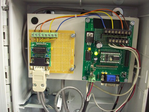
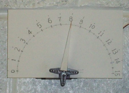
The receiving station consists of a BS2 on a Basic Stamp Super Carrier Board connected to the radio modem via MAX232 serial line converter. The level indicator is a analog hobby servo with a pointer on a scaled index card. As a added bonus, it is also connected to another BS2 that logs the information to a Parallax - Redi Web Server that allows us to review this logged data over our intranet. Note: It seems the Redi Web server has been replace by the "Parallax Internet Netburner Kit" (PINK), although it does appear to interface with the Basic Stamp in a similar manner as the Redi Web Server.
Notes:
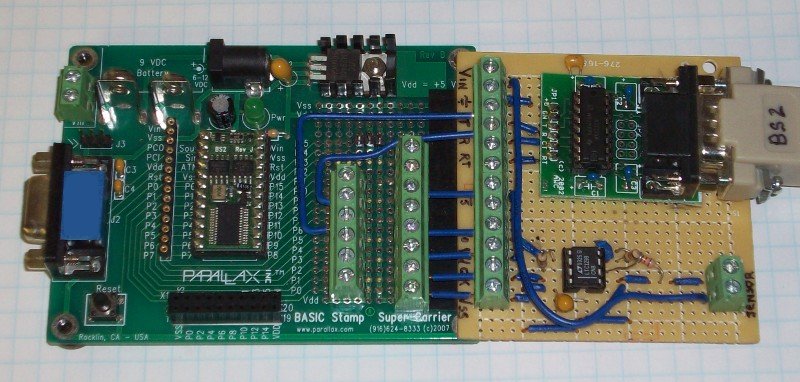
The project uses the Basic Stamp 2 Micro-controller mounted on the Super Carrier Board (SCB) which has two arrays of screw terminal blocks mounted in the proto - board area on the SCB. The terminal block array closest to the BS2 connects to the some of the even numbered pins, some to Vdd and Vss. The opposite terminal block array connects to some of the odd numbered pins, some to Vdd and Vss.
The unused pins not connected to the terminal blocks are accessible through the app mod header. This design was used for a few reasons. I have a few other projects in house that use this same SCB layout. It easy to "swap out" the boards if needed – so it maintains compatibility. It also makes it easy for a secure wire "hook-ups" during project development. The other note to mention is the use of the Serial Interface Adaptor. The original prototype used a MAX202 IC on a proto board with screw terminal blocks. Although not as economical, I wanted to go with the db9 connectors and cables, so I chose to use the pre-made Serial Interface Adaptor as a matter of convenience.
Main Components:
Parts Common to all locations:
Basic Stamp 2
Basic Stamp Super Carrier Board
BS2 – Data Radio Transmitter:
LTC1298 Parallax No. 604-00001 w App Kit Documentation
· Ashcroft Pressure Transducer T27M0242EW30#GXCY Available from www.grainger.com No. 2AGC2
· RS-I serial adapter from www.awce.com
· Raveon's RV-M5 FireLine wireless transceiver from www.raveontech.com
· Quarter wave ground plan antenna , home made - www.hamuniverse.com/2metergp.html
· 45 Watt Solar Panel Kit from Harbor Freight No. ITEM 90599-3VGA
· 12V DC 18 Ah sealed gel cell from www.eastpenn-deka.com No. 8GU1
BS2 – Data Radio Receiver:
· Parallax (Futaba) Standard Servo No. 900-00005
· Raveon's RV-M5 FireLine wireless transceiver available from www.raveontech.com
· Quarter wave ground plan antenna , home made - www.hamuniverse.com/2metergp.html
· RS-I serial adapter from www.awce.com
· Generic 12 VDC Linear Power Supply
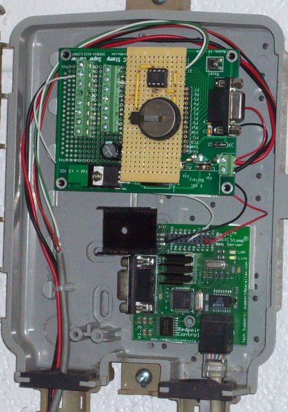
BS2 Host – Redi Web Server
· DS1302 IC Parallax No. 604-00005
· 32.768 kHz Series Crystal Parallax No. 251-03230
· 3 V. Coin Cell with holder
· Parallax 20-pin Header No. 450-02003 (to connect the 1302 protoboard to the app mod header on the SCB)
· Parallax Redi Basic Stamp Web Server (No longer available ?) replaced with -
· PINK (Parallax Internet Netburner Kit) No. 30013
Program Descriptions:
These programs are not optimized or written using the most efficient use of program space. They may contain redundant instructions of Pbasic and a generous use of the variables. I will modify as future needs require. As for now, it helps with the program flow, especially if there is the need for modifications in the future. The Pbasic programs are all commented to aid in interpreting the program flow.
BS2 – Data Radio Transmitter.bs2
At start up, data is polled from the LTC1298 and is sent out on the DEBUG screen.
This aids in setting the ratio value used to convert the LTC1298 data to feet (measured in tenths). The main program loops 4 times pausing about 3 minutes between loops. During each loop the Check_PT subroutine is called which polls the LTC1298 and then the polled result is converted to a value equivalent to the level data measured in tenths of a foot. This value is then compared to the previous polled value. IF the sum or difference is greater then three tenths, THEN exit the loop and send the data to the radio-modem. This is an exception and may indicate abnormal changes in data.
After 4 loops or approximately 12 minutes the the data is sent out to the radio modem – via the sendData subroutine, and then returns to the start of the main program loop.
·Subroutines
Check_PT: subroutine polls the LTC 1298 eight times pausing 500 ms between polls and then averaging the result. The circuit and the core subroutine is from the Parallax AppKit, "Using the LTC1298 12bit Analog-to-Digital Converter". At this time, only one channel is being utilized, the other is tied to ground via 10k ohm resistor. In the future, this may be used to monitor the solar cell battery voltage.
Calculate: Converts the output value of the LTC1298 to the level value measured in tenths of a foot. Both the level and the LTC1298 are linear, it is just a ratio calculation – so no magic here.
SendData: subroutine starts by taking the radio out of "sleep mode". The BS2 sends a SEROUT "AS" to the second radio-modem at the monitoring location, and then for listen (20 seconds) for a SERIN reply of "LS". The BS2 will SEROUT the level data. The radio is put back into sleep mode and returns to the main program. If the radio does not receive an "LS" within 20 seconds it will try again four times before exiting the subroutine and return to the main program loop.
·BS2 – Data Radio Receiver.bs2
The main loop starts with the SERIN listening for "AS" sent from the remote transmitter. If after 60 seconds ,"AS" is not received, it will go to the label, noData:, which will increment the variable wdCount by 1 and return to the SERIN to wait again for "AS". IF wdCount exceeds 255, it will go to to the subroutine WatchDog,
When an "AS" is received, the BS2 will reply with a SEROUT of "LS" to the radio-modem.
The BS2 will then listen for the level data to be sent by the remote transmitter. Once the level data is received, it is tested to see if the data is valid. If data is not received in 20 seconds or the value is not valid, it will go to the subroutine WatchDog.
If a valid level is received, it will be passed on to the "Calculate" subroutine, which will convert the level value to the value needed to position the server pointer to the indexed value on the indicator card.
The next subroutine, "SendData" will make the level value available to update the BS2 Host - Redi web server. The program then return to the start of the main program loop.
Subroutines:
Calculate: Converts the received level value to the value needed to position the server pointer to the indexed equivalent value on the indicator card.
ServoOut: Positions the pointer connected to the servo horn to the index value on the indicator card.
SendData will make the level value available to update the BS2 Host - Redi web server. The subroutine uses the SEROUT command with a flow pin modifier. It will wait 30 seconds for a go signal from the the BS2 host which should occur about every twenty seconds. If it does receive a go signal within 30 seconds, the subroutine will return to the beginning of the main program loop.
WatchDog: which will set servo indicator to 15 and send out the value 255 to the BS2 Host to the REDi web server. The BS2 Web Host will interpret the value 255 as "No Data Available". Note: The values 15 and 255 can not be reached because the physical maximum level is about fourteen feet. On the indicator scale, the15 should be replaced with a question mark..
BS2 Host – Redi Web Server.bs2
The BS2 – Redi Web Server has been in service for about year and half. It displayed the level data from another location, (that uses leased lines for data communication) which also incorporates the use of the BS2 micro-controllers. The Redi Web Server now allows us to view the data from both locations over our system's intranet. The web page consists of a table with two columns, each column displays the current and logged data from each location.
The first writing of this program used a lot of variables for the Redi write subroutines which were shared for each location column. The program flow became difficult to follow. In the rewrite, subroutines were duplicated for each column. What is interesting, is both programs (both without DEBUG statements) ended up using about 85% of the BS2's programming space. I added DEBUG instructions to display the various variables during the BS2 program execution, this added about 10% to the program's memory use. I have included a screen capture of the Web page along with the actual HTML code so the use of the Redi variables can be observed.
The program starts out with an option to set the DS1302's date and time. Once set, it is maintained by a back up coin cell in the event of a temporary power interruption.
The values are initialized for unknown data and is written to the Redi web server. The main program loop has two parts, one for each data location and each data location corresponds to each column displayed by the Redi web server. The first part of the main program waits (15 secs) for incoming data from the BS2 at Location 1 (which sends it serial data out in cycles less then 15 secs). Once the Data is received it is compared for valid data, or a change in value from the previous data and if so, written to the Redi web server. A log counter is incremented by one, once the log counter reaches a set value (about every 20 minutes), the data is logged along with the current date and time. (date and time are updated for the most recent logged data only). If no incoming data is received within 15 seconds a counter is incremented and it moves on to the get the data for Location two. If this counter reaches a set value, indicating data is not being sent by the Location BS2 for whatever reason, the Redi web server will be updated to display "Unknown, Data not available". The second part of the program for Location 2 works the same way. The only difference is the SERIN uses a flow control pin. This is because Location 2 BS2 may only have data available about every twelve minutes. When BS2 host for Location 2 has new data, the SEROUT and flow control pin will wait 30 seconds for the BS2 Redi host to receive it. The BS2 Redi host main program loops no more than every 20 seconds.
The Pbasic programs are all commented to aid in interpreting the program flow.
Project Description:
The goal of this project is to monitor level data located in a remote location that is not serviced by electric utilities or land line telephone.
Remote monitoring is not new, and there are a number of commercial systems already available for this purpose. Most of these systems use cellular, or radio transceivers using the 900 megahertz or the gigahertz band segments for wireless communications. These higher frequency bands work great for line of sight communications, however, for remote locations with dense foliage, it was not reliable. While doing further research for this project, I came across radio-modems using the license free Multi-Use Radio Service (MURS) frequency's that provided a wireless RS-232 serial communications link – which is ideal for the Basic Stamp.
Circuit Descriptions:
The remote location is monitored with a standard 4 – 20 milliamp current loop, 0 – 30 PSIG pressure transducer, via an LTC1298 analog to digital converter connected to the Basic Stamp Super Carrier Board. The digital output from the LTC1298 is then converted to feet by the BS2 and transmitted via MAX232 serial line converter to the radio modem. The equipment is powered by a solar cell charged battery.
The receiving station consists of a BS2 on a Basic Stamp Super Carrier Board connected to the radio modem via MAX232 serial line converter. The level indicator is a analog hobby servo with a pointer on a scaled index card. As a added bonus, it is also connected to another BS2 that logs the information to a Parallax - Redi Web Server that allows us to review this logged data over our intranet. Note: It seems the Redi Web server has been replace by the "Parallax Internet Netburner Kit" (PINK), although it does appear to interface with the Basic Stamp in a similar manner as the Redi Web Server.
Notes:
The project uses the Basic Stamp 2 Micro-controller mounted on the Super Carrier Board (SCB) which has two arrays of screw terminal blocks mounted in the proto - board area on the SCB. The terminal block array closest to the BS2 connects to the some of the even numbered pins, some to Vdd and Vss. The opposite terminal block array connects to some of the odd numbered pins, some to Vdd and Vss.
The unused pins not connected to the terminal blocks are accessible through the app mod header. This design was used for a few reasons. I have a few other projects in house that use this same SCB layout. It easy to "swap out" the boards if needed – so it maintains compatibility. It also makes it easy for a secure wire "hook-ups" during project development. The other note to mention is the use of the Serial Interface Adaptor. The original prototype used a MAX202 IC on a proto board with screw terminal blocks. Although not as economical, I wanted to go with the db9 connectors and cables, so I chose to use the pre-made Serial Interface Adaptor as a matter of convenience.
Main Components:
Parts Common to all locations:
Basic Stamp 2
Basic Stamp Super Carrier Board
BS2 – Data Radio Transmitter:
LTC1298 Parallax No. 604-00001 w App Kit Documentation
· Ashcroft Pressure Transducer T27M0242EW30#GXCY Available from www.grainger.com No. 2AGC2
· RS-I serial adapter from www.awce.com
· Raveon's RV-M5 FireLine wireless transceiver from www.raveontech.com
· Quarter wave ground plan antenna , home made - www.hamuniverse.com/2metergp.html
· 45 Watt Solar Panel Kit from Harbor Freight No. ITEM 90599-3VGA
· 12V DC 18 Ah sealed gel cell from www.eastpenn-deka.com No. 8GU1
BS2 – Data Radio Receiver:
· Parallax (Futaba) Standard Servo No. 900-00005
· Raveon's RV-M5 FireLine wireless transceiver available from www.raveontech.com
· Quarter wave ground plan antenna , home made - www.hamuniverse.com/2metergp.html
· RS-I serial adapter from www.awce.com
· Generic 12 VDC Linear Power Supply
BS2 Host – Redi Web Server
· DS1302 IC Parallax No. 604-00005
· 32.768 kHz Series Crystal Parallax No. 251-03230
· 3 V. Coin Cell with holder
· Parallax 20-pin Header No. 450-02003 (to connect the 1302 protoboard to the app mod header on the SCB)
· Parallax Redi Basic Stamp Web Server (No longer available ?) replaced with -
· PINK (Parallax Internet Netburner Kit) No. 30013
Program Descriptions:
These programs are not optimized or written using the most efficient use of program space. They may contain redundant instructions of Pbasic and a generous use of the variables. I will modify as future needs require. As for now, it helps with the program flow, especially if there is the need for modifications in the future. The Pbasic programs are all commented to aid in interpreting the program flow.
BS2 – Data Radio Transmitter.bs2
At start up, data is polled from the LTC1298 and is sent out on the DEBUG screen.
This aids in setting the ratio value used to convert the LTC1298 data to feet (measured in tenths). The main program loops 4 times pausing about 3 minutes between loops. During each loop the Check_PT subroutine is called which polls the LTC1298 and then the polled result is converted to a value equivalent to the level data measured in tenths of a foot. This value is then compared to the previous polled value. IF the sum or difference is greater then three tenths, THEN exit the loop and send the data to the radio-modem. This is an exception and may indicate abnormal changes in data.
After 4 loops or approximately 12 minutes the the data is sent out to the radio modem – via the sendData subroutine, and then returns to the start of the main program loop.
·Subroutines
Check_PT: subroutine polls the LTC 1298 eight times pausing 500 ms between polls and then averaging the result. The circuit and the core subroutine is from the Parallax AppKit, "Using the LTC1298 12bit Analog-to-Digital Converter". At this time, only one channel is being utilized, the other is tied to ground via 10k ohm resistor. In the future, this may be used to monitor the solar cell battery voltage.
Calculate: Converts the output value of the LTC1298 to the level value measured in tenths of a foot. Both the level and the LTC1298 are linear, it is just a ratio calculation – so no magic here.
SendData: subroutine starts by taking the radio out of "sleep mode". The BS2 sends a SEROUT "AS" to the second radio-modem at the monitoring location, and then for listen (20 seconds) for a SERIN reply of "LS". The BS2 will SEROUT the level data. The radio is put back into sleep mode and returns to the main program. If the radio does not receive an "LS" within 20 seconds it will try again four times before exiting the subroutine and return to the main program loop.
·BS2 – Data Radio Receiver.bs2
The main loop starts with the SERIN listening for "AS" sent from the remote transmitter. If after 60 seconds ,"AS" is not received, it will go to the label, noData:, which will increment the variable wdCount by 1 and return to the SERIN to wait again for "AS". IF wdCount exceeds 255, it will go to to the subroutine WatchDog,
When an "AS" is received, the BS2 will reply with a SEROUT of "LS" to the radio-modem.
The BS2 will then listen for the level data to be sent by the remote transmitter. Once the level data is received, it is tested to see if the data is valid. If data is not received in 20 seconds or the value is not valid, it will go to the subroutine WatchDog.
If a valid level is received, it will be passed on to the "Calculate" subroutine, which will convert the level value to the value needed to position the server pointer to the indexed value on the indicator card.
The next subroutine, "SendData" will make the level value available to update the BS2 Host - Redi web server. The program then return to the start of the main program loop.
Subroutines:
Calculate: Converts the received level value to the value needed to position the server pointer to the indexed equivalent value on the indicator card.
ServoOut: Positions the pointer connected to the servo horn to the index value on the indicator card.
SendData will make the level value available to update the BS2 Host - Redi web server. The subroutine uses the SEROUT command with a flow pin modifier. It will wait 30 seconds for a go signal from the the BS2 host which should occur about every twenty seconds. If it does receive a go signal within 30 seconds, the subroutine will return to the beginning of the main program loop.
WatchDog: which will set servo indicator to 15 and send out the value 255 to the BS2 Host to the REDi web server. The BS2 Web Host will interpret the value 255 as "No Data Available". Note: The values 15 and 255 can not be reached because the physical maximum level is about fourteen feet. On the indicator scale, the15 should be replaced with a question mark..
BS2 Host – Redi Web Server.bs2
The BS2 – Redi Web Server has been in service for about year and half. It displayed the level data from another location, (that uses leased lines for data communication) which also incorporates the use of the BS2 micro-controllers. The Redi Web Server now allows us to view the data from both locations over our system's intranet. The web page consists of a table with two columns, each column displays the current and logged data from each location.
The first writing of this program used a lot of variables for the Redi write subroutines which were shared for each location column. The program flow became difficult to follow. In the rewrite, subroutines were duplicated for each column. What is interesting, is both programs (both without DEBUG statements) ended up using about 85% of the BS2's programming space. I added DEBUG instructions to display the various variables during the BS2 program execution, this added about 10% to the program's memory use. I have included a screen capture of the Web page along with the actual HTML code so the use of the Redi variables can be observed.
The program starts out with an option to set the DS1302's date and time. Once set, it is maintained by a back up coin cell in the event of a temporary power interruption.
The values are initialized for unknown data and is written to the Redi web server. The main program loop has two parts, one for each data location and each data location corresponds to each column displayed by the Redi web server. The first part of the main program waits (15 secs) for incoming data from the BS2 at Location 1 (which sends it serial data out in cycles less then 15 secs). Once the Data is received it is compared for valid data, or a change in value from the previous data and if so, written to the Redi web server. A log counter is incremented by one, once the log counter reaches a set value (about every 20 minutes), the data is logged along with the current date and time. (date and time are updated for the most recent logged data only). If no incoming data is received within 15 seconds a counter is incremented and it moves on to the get the data for Location two. If this counter reaches a set value, indicating data is not being sent by the Location BS2 for whatever reason, the Redi web server will be updated to display "Unknown, Data not available". The second part of the program for Location 2 works the same way. The only difference is the SERIN uses a flow control pin. This is because Location 2 BS2 may only have data available about every twelve minutes. When BS2 host for Location 2 has new data, the SEROUT and flow control pin will wait 30 seconds for the BS2 Redi host to receive it. The BS2 Redi host main program loops no more than every 20 seconds.
The Pbasic programs are all commented to aid in interpreting the program flow.
800 x 382 - 109K
505 x 379 - 72K
413 x 589 - 88K
492 x 545 - 67K
449 x 324 - 39K
Comments