

Controlling a 12V circuit
 sylvie369
Posts: 1,622
sylvie369
Posts: 1,622
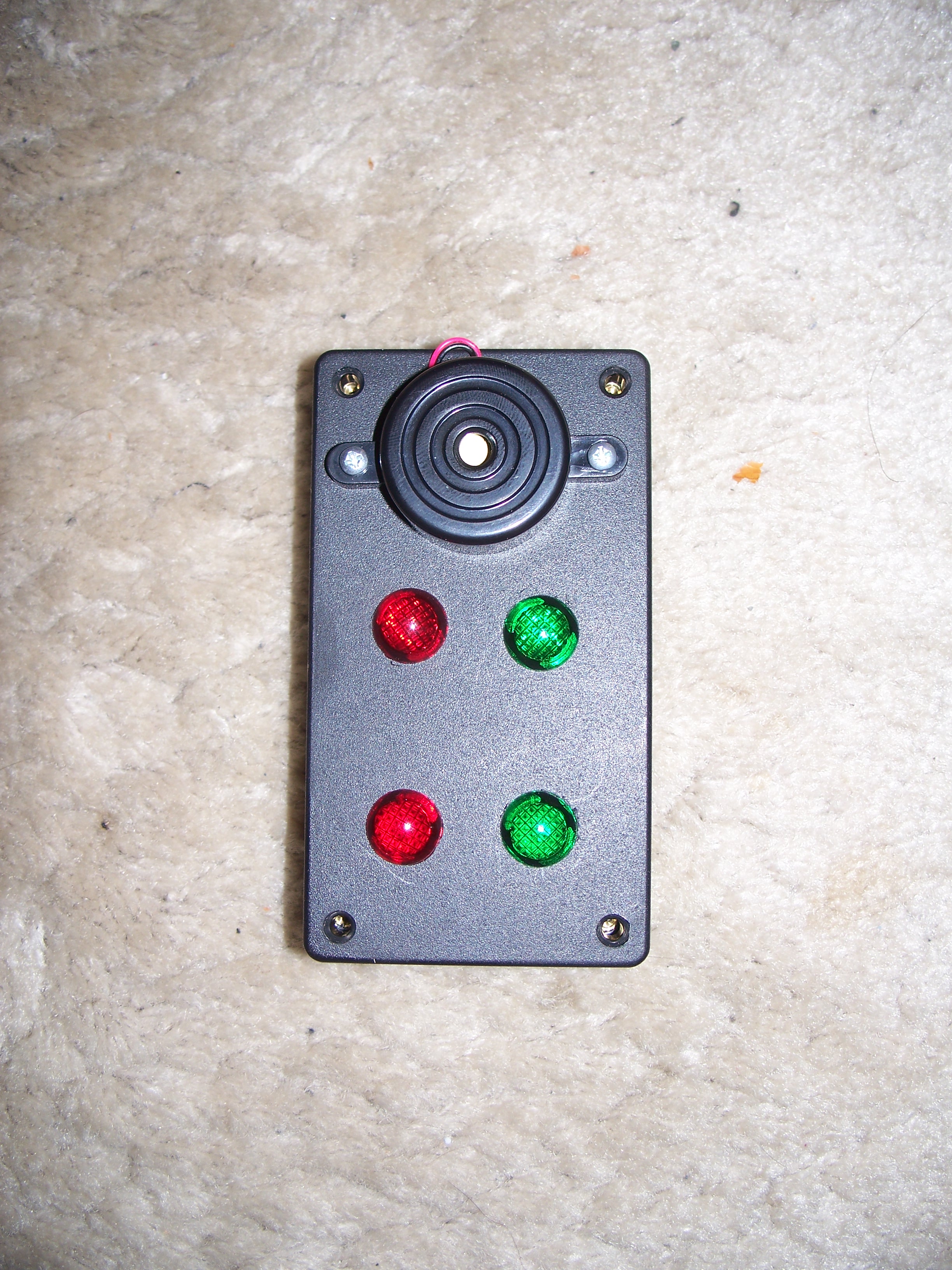
I want to use the output of five Propeller pins (from a protoboard) to control 5 12V devices. Four of the devices are simple lights, specifically these:
http://www.radioshack.com/product/index.jsp?productId=2062367
The other device is a piezo buzzer:
http://www.radioshack.com/product/index.jsp?productId=2062398#tabsetBasic
I'll need to be able to turn each device on and off separately. If it makes any difference, only two of the lights will be on at a time.
Assuming that the code needed will be just a matter of setting pins as outputs and then setting them high or low as necessary, I can handle the programming part. What am I going to need in the way of hardware? I'd like to keep it simple, of course. I assume that the 12V circuit powering the devices will need to be on the same ground as the Prop that will control them. I also assume that I can wire the grounds of all of the devices together.
This is for my rocket telemetry project. I want two red lights lit while the pull-pins are connected, and then those will go off and green lights will go on when the pull-pins (which indicate that the parachutes have deployed) are pulled. I also want the buzzer to sound briefly when the rocket reaches apogee, and again when each of the parachutes comes out, and then a longer buzz when the rocket lands. Again, the programming part is no problem. This is so I can watch the rocket instead of the little LCD screen where I'm currently displaying those events.
Post Edited (sylvie369) : 4/6/2010 11:09:32 PM GMT
2448 x 3264 - 2M
Comments
It states that the buzzer will run on 4-24V, and will draw 5mA at 12. Try supplying 5VDC to the buzzer to see if it is loud enough for what you
want to do. If so, run it on 5V, and replace the lights with LEDs. This arrangement would be much easier to implement. Otherwise, you'll have
to use transistors. You already have 5V; from the supply you are using for the Prop.
If need be, you could use optoisolators with current limiting resistors on the 12V side, and these would switch things on the Prop side of things.
Hope this helps. More information would help regarding where the 12Vs is coming from.
▔▔▔▔▔▔▔▔▔▔▔▔▔▔▔▔▔▔▔▔▔▔▔▔
"She may not be very pretty now, but she was somebody's baby once." Bugs Bunny
I'm not that confident that I'll be able to see LEDs in the direct sunlight that we occasionally get out on the rocket range, though I'm not really sure I'll see these either. They're really dim at 5V.
I still would like to see what the transistorized circuit would look like. If it's just connecting some 3904s, resistors and diodes·to each of the devices·that's not really a problem.
The 12V will come from a portable battery (a Celestron Powertank, specifically). I'm also using it for a 7.5V input to power the Protoboard/LCD - I've used that out on the field already, on the first flight of this setup. My issue here isn't the power supply, it's interfacing the Prop to devices using 12V.
The ULN2803A is a high-voltage, high-current Darlington transistor array. The device consists of eight npn Darlington pairs that feature high-voltage outputs with common-cathode clamp diodes for switching inductive loads. The collector-current rating of each Darlington pair is 500 mA. The Darlington pairs may be connected in parallel for higher current capability.
It's pretty easy to interface.· I think it would work.
Chuck
A 1K base resistor will give you about 3mA of base current. If the transistor has a gain of 33, that'll give you an output current of around 100mA. A 330 Ohm resistor will give you a collector current of maybe 300mA.
_richard
I tought that transistor gain was a very varying paramater... is there any transistors that have a low hfe range, so that it is predictable?
▔▔▔▔▔▔▔▔▔▔▔▔▔▔▔▔▔▔▔▔▔▔▔▔
Style and grace : Nil point
The drawing shows both the buzzer and lamp on the same circuit because they're both hooked up exactly the same. Of course you would need five transistors and five resistors--for your five 12 volt devices.
Jameco pricing is $0.02/resistor and 0.05/transistor. So you're looking at 7 cents each, a 35 cent outlay of cash for five such circuits.
--Steve
EDIT: Oops.. forgot the diode... Add another nickel to the total price
Post Edited (w8an) : 4/8/2010 3:08:44 AM GMT
▔▔▔▔▔▔▔▔▔▔▔▔▔▔▔▔▔▔▔▔▔▔▔▔
"She may not be very pretty now, but she was somebody's baby once." Bugs Bunny