

CNC machine powered by propeller - contest submission
 Chris_D
Posts: 305
Chris_D
Posts: 305
Hi folks,
I posted this on some of the other forums but thought that I should expose it here too.··Even though I ·submitted this for the contest and lost , I still felt I should present it to demonstrate what can be done with a prop.· Note, this is NOT the CNC machine that got the special recognition award.
Here are some particulars about the machine...
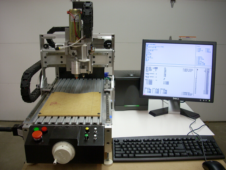
This project is a 3 axes CNC (Computer Numerical Control) machine and control. The goal of the project was to create a stand alone CNC control that has performance comparable to existing hobby-level, PC based CNC controls.· Being “stand alone”, this control could not use a PC to provide any functionality, all functions and logic must be controlled by microcontrollers.·
·
The performance goals were to have a closed loop system using linear quadrature encoder scales for positional feedback which exceeds the capabilities of several PC based controls.· The targeted stepping frequency was to exceed 100,000 steps per second, again rivaling PC based control performance.· Low cost was also a primary goal as it didn’t make any sense to design a controller more expensive than a PC & software combination.· The Propeller chip was the key component to make the system possible for performance and low cost.
·
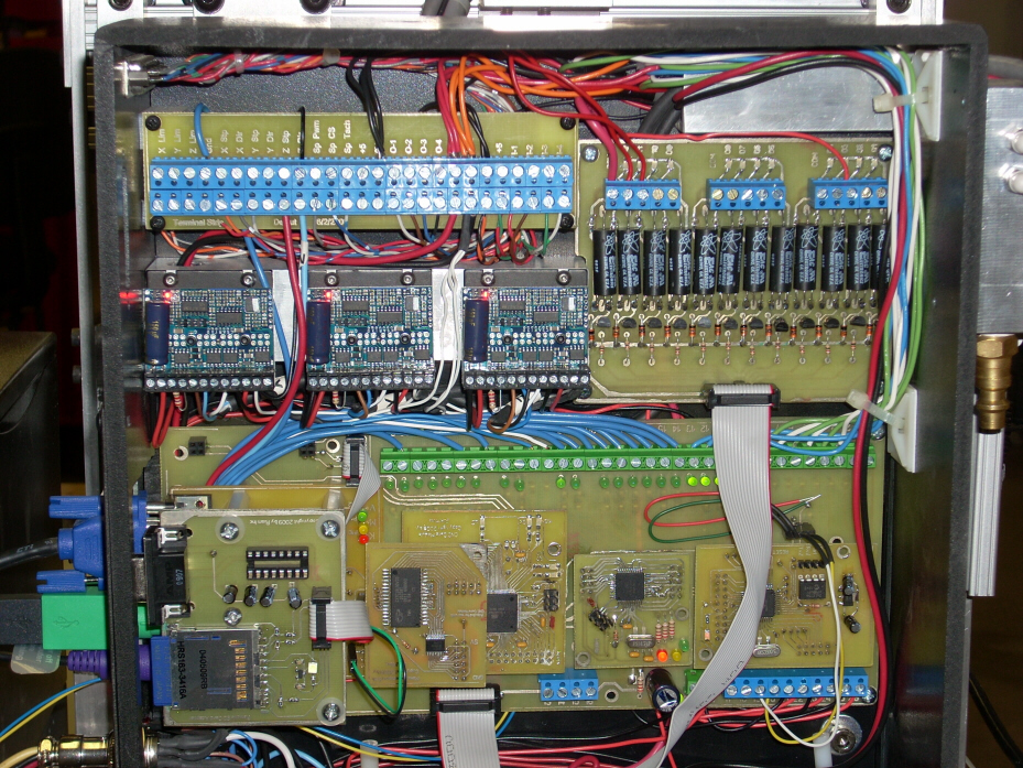
The CNC controller is made up of 4 modules, two of which are Propeller controlled modules
The Propeller chips solved two different sets of problems to make this project possible.·
·
Keyboard, Mouse, and Video Interface Module Description - Brief
One of the primary goals of the project was to eliminate the need for a host PC as the CNC control or even for its user interface.· As this project was to run completely on microcontrollers, a suitable interface was required and a VGA display seemed optimal.· The Propeller was an ideal choice to provide the user interface. It is not only a very economical solution, but also a solution that would allow me to customize it to work the way I wanted it to.
·
Motion Control Sequencing Description - Brief
A CNC machine requires precision timing for the motions on all axes.· Previous attempts to do it with a single tasking microcontroller worked, but performance lacked.· During a motion, all 3 axes must move at the same time, possibly at different frequencies (velocities), yet in perfect synchronization.· Furthermore, velocity must change dynamically with acceleration / deceleration profiles, limit switches need to be monitored, and positional feedback must be tracked.· The best solution was the Propeller chip as it provided 8 COGs, each of which can communicate easily with centralized memory for easy data sharing.· With the 8 COGs, I could devote a COG to each axis to maintain signal timing, and use the rest of the COGs to handle the other tasks such as: Serial communications, Velocity control, Positional tracking via linear quadrature scales for closed loop operation
Keyboard, Mouse, and Video Unit
The KMV allows the user to input data and to view the status and information within the CNC core.· The Propellers native hardware and existing objects made this the perfect choice for the man-machine interface.· Using off-the-shelf objects for keyboard, mouse, and Hi-Res VGA text output, the only additional code needed was to create a simple interface between the CNC Core and the KMV.· Using another off-the-shelf object, the Full Duplex Serial object, serial communications was a snap to do. Simple commands are used to display video on the VGA monitor and keyboard / mouse data is sent back to the CNC Core.· The Propeller’s native video output hardware greatly simplified the hardware interface to these devices (Keyboard, Mouse, and VGA monitor).
·

Motion Control Unit
The MCU accepts motion data from the MPU and executes that motion data with precise timing to cause synchronized motion on 3 axes.· Motion data is provided in the form of position to move to, velocity, acceleration rate, and deceleration rate.· The MCU will dynamically adjust velocity at the commanded acceleration rates from the running velocity to the desired velocity.· The output signals are for industry standard step and direction type stepper or servo drives.· Positional feedback is provided by linear quadrature encoder.· The encoder data is fed into the motion routine which in turn uses that as the step output counter.· An accumulator tracks the deviation between output steps and feedback position that can be used to determine if an axis has stalled.· Depending on the mode of operation, limit switch inputs can be used as either a home position switch or as a over travel limit switch.
·

·These links take you to some videos which explain in a bit more detail the control and machine as well as some video of it actually interpeting a CNC program and running cycles.
Control overview...
http://www.youtube.com/watch?v=PSuObtH2Tng
Machine overview...
http://www.youtube.com/watch?v=ybEraG8FeP8
Machine running cycles...
http://www.youtube.com/watch?v=HF1Z9evXor0
This project has been a long term project (so far about 1 1/2 years I think).· Since submitting the project for the contest, I have started the second stage of optimization of the motion algorithms and have made good progress.·The new algorithms will be more efficient (faster) and more accurate (tighter synchronization of multiple axis moves).·Even though the motion specific routines were in·PASM in the last·version, the new algorithms so far have impressed me with their efficiency. ·I will probably still be working on the code for a long time yet as there are so many things I want to add to it.·
For those of you attending the expo in Ottowa IL this May, I hope to be bringing the machine there. Not sure what the status of it will be (how much functionality it will have at that moment), but it should provide for some interesting conversation.
Chris
I posted this on some of the other forums but thought that I should expose it here too.··Even though I ·submitted this for the contest and lost , I still felt I should present it to demonstrate what can be done with a prop.· Note, this is NOT the CNC machine that got the special recognition award.
Here are some particulars about the machine...
This project is a 3 axes CNC (Computer Numerical Control) machine and control. The goal of the project was to create a stand alone CNC control that has performance comparable to existing hobby-level, PC based CNC controls.· Being “stand alone”, this control could not use a PC to provide any functionality, all functions and logic must be controlled by microcontrollers.·
·
The performance goals were to have a closed loop system using linear quadrature encoder scales for positional feedback which exceeds the capabilities of several PC based controls.· The targeted stepping frequency was to exceed 100,000 steps per second, again rivaling PC based control performance.· Low cost was also a primary goal as it didn’t make any sense to design a controller more expensive than a PC & software combination.· The Propeller chip was the key component to make the system possible for performance and low cost.
·
The CNC controller is made up of 4 modules, two of which are Propeller controlled modules
- Keyboard, Mouse, and Video (KMV) Interface Module - Propeller
- CNC Core – Atmega· 2560
- Motion Profiler Unit (MPU) – Atmega644P
- Motion Controller Unit (MCU) – Propeller
The Propeller chips solved two different sets of problems to make this project possible.·
·
Keyboard, Mouse, and Video Interface Module Description - Brief
One of the primary goals of the project was to eliminate the need for a host PC as the CNC control or even for its user interface.· As this project was to run completely on microcontrollers, a suitable interface was required and a VGA display seemed optimal.· The Propeller was an ideal choice to provide the user interface. It is not only a very economical solution, but also a solution that would allow me to customize it to work the way I wanted it to.
·
Motion Control Sequencing Description - Brief
A CNC machine requires precision timing for the motions on all axes.· Previous attempts to do it with a single tasking microcontroller worked, but performance lacked.· During a motion, all 3 axes must move at the same time, possibly at different frequencies (velocities), yet in perfect synchronization.· Furthermore, velocity must change dynamically with acceleration / deceleration profiles, limit switches need to be monitored, and positional feedback must be tracked.· The best solution was the Propeller chip as it provided 8 COGs, each of which can communicate easily with centralized memory for easy data sharing.· With the 8 COGs, I could devote a COG to each axis to maintain signal timing, and use the rest of the COGs to handle the other tasks such as: Serial communications, Velocity control, Positional tracking via linear quadrature scales for closed loop operation
Keyboard, Mouse, and Video Unit
The KMV allows the user to input data and to view the status and information within the CNC core.· The Propellers native hardware and existing objects made this the perfect choice for the man-machine interface.· Using off-the-shelf objects for keyboard, mouse, and Hi-Res VGA text output, the only additional code needed was to create a simple interface between the CNC Core and the KMV.· Using another off-the-shelf object, the Full Duplex Serial object, serial communications was a snap to do. Simple commands are used to display video on the VGA monitor and keyboard / mouse data is sent back to the CNC Core.· The Propeller’s native video output hardware greatly simplified the hardware interface to these devices (Keyboard, Mouse, and VGA monitor).
·
Motion Control Unit
The MCU accepts motion data from the MPU and executes that motion data with precise timing to cause synchronized motion on 3 axes.· Motion data is provided in the form of position to move to, velocity, acceleration rate, and deceleration rate.· The MCU will dynamically adjust velocity at the commanded acceleration rates from the running velocity to the desired velocity.· The output signals are for industry standard step and direction type stepper or servo drives.· Positional feedback is provided by linear quadrature encoder.· The encoder data is fed into the motion routine which in turn uses that as the step output counter.· An accumulator tracks the deviation between output steps and feedback position that can be used to determine if an axis has stalled.· Depending on the mode of operation, limit switch inputs can be used as either a home position switch or as a over travel limit switch.
·
·These links take you to some videos which explain in a bit more detail the control and machine as well as some video of it actually interpeting a CNC program and running cycles.
Control overview...
http://www.youtube.com/watch?v=PSuObtH2Tng
Machine overview...
http://www.youtube.com/watch?v=ybEraG8FeP8
Machine running cycles...
http://www.youtube.com/watch?v=HF1Z9evXor0
This project has been a long term project (so far about 1 1/2 years I think).· Since submitting the project for the contest, I have started the second stage of optimization of the motion algorithms and have made good progress.·The new algorithms will be more efficient (faster) and more accurate (tighter synchronization of multiple axis moves).·Even though the motion specific routines were in·PASM in the last·version, the new algorithms so far have impressed me with their efficiency. ·I will probably still be working on the code for a long time yet as there are so many things I want to add to it.·
For those of you attending the expo in Ottowa IL this May, I hope to be bringing the machine there. Not sure what the status of it will be (how much functionality it will have at that moment), but it should provide for some interesting conversation.
Chris
929 x 697 - 595K
929 x 697 - 416K
779 x 169 - 7K
780 x 211 - 12K
Comments
Can't understand why you didn't make special recognition... Definitely more geek sex appeal than my Arcade machine. [noparse]:)[/noparse]
I'm looking forward to seeing this at UPEC.
Should we come up with some large floor mats so that you can do some real demos? (easy cleanup)
OBC
▔▔▔▔▔▔▔▔▔▔▔▔▔▔▔▔▔▔▔▔▔▔▔▔
Are you Propeller Powered? PropellerPowered.com
Visit the: PROPELLERPOWERED SIG forum kindly hosted by Savage Circuits.
Thank you for sharing this great project!
T o n y
I would like to think that I can do some cutting at the expo, but this machine is very small.· I don't think we will need the mats to clean up the "mess" as it will likely be mostly dust :-)· As I won't be doing circuit boards there I am thinking I will pick up some plastic material used in engraving. If I have the time to get the material and everything else ready, I might be able to engrave some small tags or someting.
Of course, this is all dependant on how far along I get with the new motion control algorithms.· I only have a few more weekends to get ready - yikes !!!!
Chris
Chris
I am very impressed! I have got a very small mill and a lathe which I operate with an MS-DOS program called pc-nc.
Especially the moving speed is very impressing!
I consider to switch to a propeller based system too. But I have hoped that this·-a little bit more simple?- could be done with only one propeller.....
How long did you work on this project?
Christof
Thank you very much for the comments.·
I have been working on the project as a whole for about 1 1/2 years I think.· It might be a bit longer than that. I had to build the machine first, then started working on the electronics and software.· I seem to think that I got started with the Propellers last summer.·I work on it about 1 to 2 days a week as time allows.·
I too am impressed with the overall performance, the Propeller is an amazing device, especially when programmed in PASM.· I have several machines here running on the MACH CNC software which is Windows based.· That software is highly evolved now but it has run into limitations which caused me to "roll my own".·
Chris
I would be interested to see the software.
This must be microstep drivers? I had made some experiments with a microstep driver for the propeller myself.
I have learned, that·one of the greatest·difficulty is the decreasing torque with increasing speed. It would be best to use very high (dangerous) motor voltages.
Your method to use feedback is great.
I would be interested in the motor type and data too.
And what do you see as "motion profiler unit"?
I am wondering, if I can build a simple system based on sphinx and Propbasic (I am not the great assembler guy...)
· With Sphinx, a preprocessor could be made and it gives the SD-card possibilities, Editor and so on.
· The preprocessor can be used to calculate cycles, HPGL as output.
· With PropBasic the actual motor-control and an interpreter for HPGL could be made.
Christof
Lot's of questions requiring very long answers. I will try to answer as best as I can in a few minutes.
The source code will stay private for the time being - sorry. Had I won the contest it would be viewable though.·
The motors used are from Keling P/N KL23H286-20-BB. Decent sized nema 23, bipolar stepper motors.· The drives I am using are Gecko G250 drives (or 251s, whichever has the heatsink included).· They are micro stepping drives - 10 microsteps.· I am only running 35 volts but would certainly like to go higher - 60 or even 70 volts.· Higher volts with steppers isn't such a bad thing - especially with a good drive.
All steppers, regardless of drive (micro or full step), lose torque at high speed.·You have to balance·your top speed desired with voltage and mechanical capabilities.· In other words, everything influences top speed, not just the motor, or the drive.· Mechanics play an important role - especially mass.
Yes, using feedback is something I mandated in this control design.· This is the one thing I really disslike about the available hobby controllers.· Again, the prop makes it easy with an available object and making the linear scales was pretty easy with parts from US Digital.
I have never used either sphinx or propbasic.· I started out using just spin to test things and then moved onto PASM.· As it turns out, PASM on the prop is relatively easy - especially if you have Viewport to help see what is going on.
As mentioned in the videos, the system I came up with uses the Atmega2560 as the "CNC".· It handles the editing, screen information generation, CNC program interpretation, SD card interfacing, etc.· Human I/O is handled via serial commands from the CNC to the KMV interface module (Propeller).
Once the CNC command is interpreted by the CNC, it passes the geometry and the velocity data to the Motion Profiller Unit (MPU).· The MPU then translates the user coordinate data into machine coordinates (Inches to steps). It also translates velocity from IPM to Steps per second) and applies the velocity ramping for accell and decel.· This data is then passed onto the Motion Control Unit (MCU)
The MCU is another propeller which accepts motion data and executes it by creating the step and direction outputs needed for the Gecko drives.· Time delays are used to control the velocity to the rate specified.
Obviously there is MUCH more going on, but that gives you an overall look at how a CNC command works through the system down to the motors.
Chris
I just watched all 3 videos- also very well done.
Hanno
▔▔▔▔▔▔▔▔▔▔▔▔▔▔▔▔▔▔▔▔▔▔▔▔
Co-author of the official Propeller Guide- available at Amazon
Developer of ViewPort, the premier visual debugger for the Propeller (read the review here, thread here),
12Blocks, the block-based programming environment (thread here)
and PropScope, the multi-function USB oscilloscope/function generator/logic analyzer
Frankly I owe you a lot of thanks for your excellant product!· Without Viewport I wouldn't be nearly as far along as I am now.·
Chris
I have looked into the datasheet of the motors, as often no info about the torque over speed... But of course the motors a big for the machine.
Great project! Thank you very much for sharing it! It is a pity, that only a few projects a presented. One can always learn from these projects and for you, the preparation of the contest has been some work too!
Well, as a matter of fact, I will have your speed in mind, when I will be waiting for my lathe to move in "rapid" feed....... It is ugly, that everything is sooo slow if you are just waiting and have nothing to do....
Good chipping!
Christof
▔▔▔▔▔▔▔▔▔▔▔▔▔▔▔▔▔▔▔▔▔▔▔▔
Links to other interesting threads:
· Home of the MultiBladeProps: TriBlade,·RamBlade,·SixBlade, website
· Single Board Computer:·3 Propeller ICs·and a·TriBladeProp board (ZiCog Z80 Emulator)
· Prop Tools under Development or Completed (Index)
· Emulators: CPUs Z80 etc; Micros Altair etc;· Terminals·VT100 etc; (Index) ZiCog (Z80) , MoCog (6809)·
· Prop OS: SphinxOS·, PropDos , PropCmd··· Search the Propeller forums·(uses advanced Google search)
My cruising website is: ·www.bluemagic.biz·· MultiBlade Props: www.cluso.bluemagic.biz
Yes, the motors are pretty big for this size machine if one were using some sort of lead screw to drive the axis.· I only have a screw on Z, X and Y are belt driven with only a 3:1 mechanical advantage.· So I had to have enough power to compensate for the lack of mechanical advantage.·
I was going to say that you might find some good information and source code to follow in Ed's mini mill project that got special recognition.· However, from what I can tell by looking at the source code, that system is not capable of running a CNC program at all.· Rather it appears that it can jog manually and execute two pre-defined shapes: a circle and a square.· In any case, looking through his source code might give you some ideas to start from.
As for your lathe's lack of speed - work up to it.· While it is impressive in the video and fun to brag about, speed isn't all that important.· For industrial applications, lack of speed costs companies money. For hobby applications lack of speed gives us more time to admire our creations in motion ;-)· Remember too that most of the time a CNC machine is "in the cut" and cutting speeds are often very slow by comparision to rapid rates!
Chris
Chris