

A Sine Wave DDS in PASM - Comments?
 Drone
Posts: 433
Drone
Posts: 433
Hello Everyone,
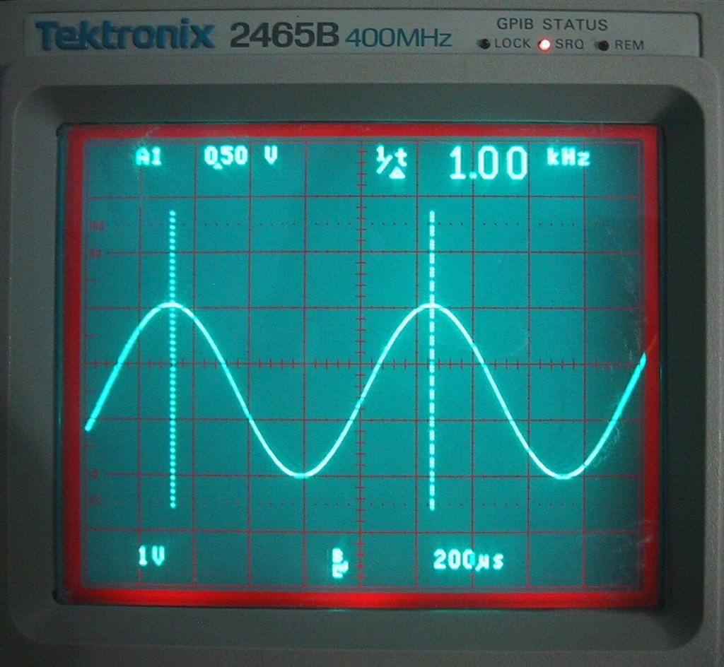
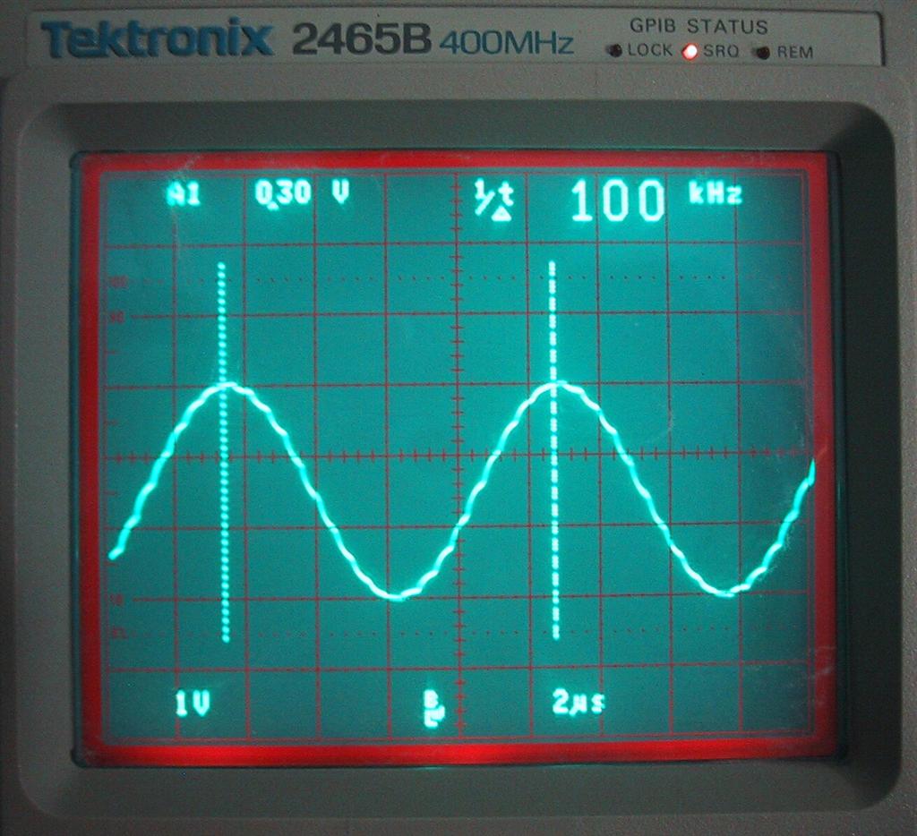
Attached is a simple 8-bit sine wave Direct Digital Synthesizer (DDS) in Propeller assembler. The DDS uses a 256 sample look-up table in cog RAM. The accumulator and tuning word are 24-bits in length. Minimum step size is 0.170Hz. With the propeller clock at 80MHz and no post-DAC filtering, the output is usable through around 150-200kHz. I'm sure you can go higher with filtering, but I haven't tried.
The heavily commented source is prefaced with a bunch of introductory documentation. A linear-weighted 8-bit R2R DAC is used, that is well documented as well. In the documentation there are external references to more information on the subject of the DDS and R2R DAC.
This object is actually quite small once you strip all the documentation out; it has to be in order to be fast. I'm no PASM expert by any means, but I would certainly like to know if anyone can make this run faster (thanks to all contributors for the suggestions so-far).
The archive includes a simple Excel 2003 spreadsheet that shows how tuning words are calculated. The look-up table can be easily modified to produce any waveform. The PASM code can be easily modified to produce square waves, triangles, ramps, etc. without a look-up table.
Perhaps I'll embellish this example with other waveforms later on. Independent I/Q output in multiple cogs is also an interesting target but I have to learn how to launch multiple cogs and keep them somewhat phase coherent.
I post this now because the object has been languishing in my to-do bin and lately someone else in the forum needed an ultrasonic sine wave generator. Any comments or suggestions are most welcome. I'll post the final version in ObEx if anyone thinks it is worth it.
Changelog:
* V1.00, 06 April 2010, first release.
* V1.01, 06 April 2010, Incorporated Kurneko's two excellent suggestions as of post time, the current V1.01 sine DDS loop uses 28 clock cycles, down from 40 cycles. This represents a 48% increase in usable output frequency. Thanks Kurneko! I have verified the number of saved clock cycles by frequency measurement. The Excel 2003 spreadsheet has been updated to allow you to do the calculation for determining number of clock cycles used from measured output frequency.
* V1.02, 06 April 2010, Error in the R2R documentation schematic fixed. The resistor to ground is 2R not R. Thanks to Toby Seckshund for pointing this out.
The attached pictures of the output waveform at 1kHz and 100kHz are for V1.00. These waveforms look about the same for V1.01 but are now at 1.5kHz and 150kHz respectively due to the reduction in clock cycles.
Best Regards, David
Post Edited (Drone) : 4/6/2010 1:45:39 PM GMT
1024 x 944 - 113K
1024 x 934 - 112K

Comments
Very impressive work, and well documented. Definitely would be a valuable addition to the obex.
I look forward to trying it very soon (gotta get some precision resistors in!)
cheers
tubular
Next thing, relocate the table to location 0 (this will save you the add Idx, #Sine instruction). All table values are effectively nops so you either accept a 1K cycle start-up delay (cognew requires 8K already) or you jump over the table and patch the first entry. Either way that's down to 32 cycles.
One more ...
entry

  '256 sampled 8-bit sine table. Replace with any sampled waveform you like
  'as long as the data table is of the same dimension and depth. Only longs are
  'used to make the DDS loop as short as possible in terms of clock cycles.

Sine          long $80,$83,$86,$89,$8C,$8F,$92,$95,$98,$9C,$9F,$A2,$A5,$A8,$AB,$AE

              ' remainder of table

              mov      dira,    PinMsk         'LSB to PA0, LSB to PA7

:loop         add      Acc,     M_             'M $1FF max if literal with #$xxx
              ror      Acc,     #16            'position index
              movs     :inline, Acc            'store 9 bit index
              andn     :inline, #%1_00000000   'clamp to 8 bit
              rol      Acc,     #16            'restore accumulator
:inline       mov      outa,    0-0            'Output 8-bits of long table lookup to DAC
              jmp      #:loop                  'Loop again

PinMsk        long     $FF                     '8-bit DAC, LSB on PA0, MSB on PA7
M_            long     0                       'Tuning word var init
Acc           long     0                       'Accumulator var init
Post Edited (kuroneko) : 4/6/2010 8:09:40 AM GMT
Tubular, IMO you don't need precision resistors just to experiment with the DAC. Usually generic 10% resistors work OK, especially if they come from the same batch. Attached are pics of a little R2R DAC board I hastily threw together. This board with 10% resistors produced the waveforms attached to the top post. The 0.1" female header is used to plug the DAC into a proto-board via jumper wires. I would recommend higher precision resistors in a production build though. I reference a nice little SIP Burr Brown R2R DAC in the documentation, half a buck if memory serves.
Regards, David
What a wonderfully useful application!
Thank you for contributing this.
On the Propeller, simply to visualise software seems enough to make it appear by magic ...
Regards,
T o n y
By the way this DDS thing can be used to verify exactly how many clock cycles the PASM loop uses. For a given tuning word measure the output frequency with a counter (or use the propeller itself as a counter!) Knowing the tuning word value and measured output frequency, the rest of the variables are known allowing us to calculate the number of clocks used via a re-arranged version of the tuning equation. I guess you could insert non-DDS PASM code into the loop to measure the difference in clocks used thereby providing exactly how many clocks are used by the inserted code. Hmmm....
It's great!!
I also think this is valuable addition to the obex.
I tried to generate higher frequency sin-wave ,too.
But I cannot.
Post Edited (caskaz) : 4/6/2010 8:51:57 AM GMT
V1.01 (see file attached to top-post) includes the two suggestions in your 4/6/2010 8:09:40 AM GMT post. Four clock cycles saved by direct port output. Eight clock cycles saved by relocating the look-up table to zero. Total savings, 12 clock cycles - down to 28 from 40. This represents a 50% increase in output frequency for a given tuning word. Quite an improvement. Thank you again!
Best Regards, David
Thank you for V1.01.
The documentation and spreadsheet are tutorials in themselves!
T o n y
▔▔▔▔▔▔▔▔▔▔▔▔▔▔▔▔▔▔▔▔▔▔▔▔
Style and grace : Nil point
:loop add Acc, M_ 'M $1FF max if literal with #$xxx ror Acc, #24 'position index movs :inline, Acc 'store 9 bit index (top bit is 0) rol Acc, #24 'restore accumulator :inline mov outa, 0-0 'Output 8-bits of long table lookup to DAC jmp #:loop 'Loop againUploaded V1.02 to the top-post; fixes this documentation error.
2. Kuroneko, thanks for your latest tip. I will study it. Not sure if I can get to it tonight my local time.
Regards, David
                mov     dira, PinMsk            ' LSB to PA0, LSB to PA7

                movi    ctra, #%0_11111_000     ' LOGIC always
                mov     phsa, M_                ' TW
                shl     phsa, #3                ' TW*8
                add     phsa, M_                ' TW*9
                shl     phsa, #1                ' TW*18
                mov     frqa, M_                ' TW == M*256/20

                mov     addr, phsa              ' -12  %%
                nop                             '  -8
                nop                             '  -4

:loop           shr     addr, #24               '  +0
                movs    :inline, addr           ' -16
                mov     addr, phsa              ' -12
:inline         mov     outa, 0-0               '  -8
                jmp     #:loop                  '  -4

PinMsk          long    $FF                     ' 8-bit DAC, LSB on PA0, MSB on PA7
M_              long    0                       ' tuning word (initialised to M*256/20)
addr            long    0
Requirements are:
- ctra is running in LOGIC always mode
- frqa is loaded with tuning word x 256 / 20
- phsa is preloaded so that the first mov (%%) would read frqa x 20 (== tuning word x 256)
256 is the result from shifting the 24 bit accumulator left 8 bits (makes addressing easier), the 1/20 is based on the cycle count between reads from phsa (you only want a single tuning word accumulation between subsequent reads).Post Edited (kuroneko) : 4/7/2010 5:55:18 AM GMT
Limitations:
* hard to set up a frequency - because the video HW uses the PLL mode, you can only adjust within one octave before changing PLL divider, etc.
* you can _NOT_ skip samples, so the waveform table length determines the maximum output frequency.
* you can only use max 8 bit output
* you must use one of the pin blocks (0..7, 8..15, 16..23, 24..31)
Benefits:
* the video HW PLL does your timing for you
* you can output 4 bytes per waitvid...in the current scheme there can be 3 instructions between waitvids, but you could unroll the loop, doubling performance
So the maximum frequency of the sine wave for this code is ~ 73kHz, but if you make the data table smaller, or unroll the loop you could seriously increase the maximum frequency.
Jonathan
▔▔▔▔▔▔▔▔▔▔▔▔▔▔▔▔▔▔▔▔▔▔▔▔
lonesock
Piranha are people too.
when I was playing around with something very similar it seemed to me that the maximum practical limit appeared to be 40msps out per second; I based this on WAITVID taking 5+ cycles.
Using 64 WAITVID's in a row, with a 64 long packed table of values (for a 256 sample waveform) it might be possible to do 64msps out, if we can trust WAITVID to take a constant 5 cycles; but to avoid jitter it might be best to use a 40MHz frequency with 255 samples, using the time of the 256th sample for a JMP to the beginning of the WAITVID sequence.
40MHz/256 samples = 156,200Hz
40MHz/200 samples = 200,000Hz
and so on...
I used 1% resistors, and I hand-sorted them to match within .1% (by measuring and binning a large enough number of resistors to get enough for an R2R ladder matched within 0.1%)
▔▔▔▔▔▔▔▔▔▔▔▔▔▔▔▔▔▔▔▔▔▔▔▔
www.mikronauts.com E-mail: mikronauts _at_ gmail _dot_ com 5.0" VGA LCD in stock!
Morpheus dual Prop SBC w/ 512KB kit $119.95, Mem+2MB memory/IO kit $89.95, both kits $189.95 SerPlug $9.95
Propteus and Proteus for Propeller prototyping 6.250MHz custom Crystals run Propellers at 100MHz
Las - Large model assembler Largos - upcoming nano operating system
In section 2 of the program documentation a website is listed as www.bournes.com. I believe this should be www.bourns.com as www.bournes.com is an an auto service site.
In the program comments in the DAT section: "mov dira, PinMsk 'LSB to PA0, LSB to PA7" I believe it should be 'LSB to PA0, MSB to PA7".
Now my question is, can it be easily changed to use pins PA16 (LSB) to PA23(MSB) instead of PA0 - PA7?
Can I just change the line "PinMsk long $FF" to "PinMsk long $00FF" ? Would the "Mov OUTA 0-0" line need to be changed?
Well I'm still new to propeller programming. That is a little over my head. I think I will re-arrange my circuit to use PA0 - PA7 instead of monkeying around with the code.
I haven't actually built the circuit yet but am just drawing the schematic.
We have been discussing Drone's (David's) code in this topic heading for the past few weeks.
http://forums.parallax.com/showthread.php?p=895566
Kodos to David and other contributors like·kuroneko who took the code from 40 to 28 and now only 20 clock cycles.· I'm greener than GreenTHHN as far as spin code is concerned, but am very impressed with what some of you can do.
GreenTHHN - PA0 to PA7 works good on the Demo board.
Fred
▔▔▔▔▔▔▔▔▔▔▔▔▔▔▔▔▔▔▔▔▔▔▔▔
________________________________
Work:www.vhf.ca··Play:www.Costalegre.ca
:sample MOV OUTA, 0-0 MOVS :sample, PHSB ANDN :sample, #$100 JMP :sampleAs for the DAC pin numbers. If I remember correctly, the V1.02 code needed the DAC to be on PA0-PA7 for minimum clock cycles. I'll revisit this in light of new comments here and the upcoming release of V1.03 using Kuroneko's brilliant counter method after a bit of beta testing.
CoronaKid, Have you had time to beat the beta V1.03 to death yet? If so, send me an Email with results if.
I've been busy with U.S. tax stuff as of late. Nightmare to say the least. Sorry if I've been late to reply. I'm also not getting reliable email notifications when this thread is updated even though I check every notification and filter all propeller email forum notifications from my spam folder to my in-box. Hmmm....
Best Regards, David
@Andrey: I toyed with the idea of chaining counters but figured that I get too many limitations for free (while preserving current functionality).
Post Edited (kuroneko) : 4/15/2010 10:16:51 AM GMT
The original code does DDS with 28 clocks and works fine but is not adjustable with out recompiling or
starting and stoping the cog it runs in.
I wanted to build a sweep generator so I modified the code to use a rdlong and pace itself with a clock
generated on pin 8 by a counter putting out a 1.25MHZ signal. The pacing was done because the
rdlong takes a variable number of clocks 7.. 22 if I remember and would cause jitter. As long as the code is
completed before the next 1.25MHZ edge I get even pacing of the DDS.
Drone's org code
VAR
long cog 'cog id
PUB start(M) : okay 'M is the tuning word
stop 'Stop DDS if it is running, frees a cog
M_ := M 'Assign passed variable (tuning word)
okay := cog := cognew(@entry,0) 'Start DDS, uses a cog.
PUB stop
if cog 'If cog is running
cogstop(cog~) 'Stop DDS, frees a cog

DAT
org 0
entry
'256 sampled 8-bit sine table. Replace with any sampled waveform you like
'as long as the data table is of the same dimension and depth. Only longs are
'used to make the DDS loop as short as possible in terms of clock cycles.

Sine long $80,$83,$86,$89,$8C,$8F,$92,$95,$98,$9C,$9F,$A2,$A5,$A8,$AB,$AE
long $B0,$B3,$B6,$B9,$BC,$BF,$C1,$C4,$C7,$C9,$CC,$CE,$D1,$D3,$D5,$D8
long $DA,$DC,$DE,$E0,$E2,$E4,$E6,$E8,$EA,$EC,$ED,$EF,$F0,$F2,$F3,$F5
long $F6,$F7,$F8,$F9,$FA,$FB,$FC,$FC,$FD,$FE,$FE,$FF,$FF,$FF,$FF,$FF
long $FF,$FF,$FF,$FF,$FF,$FF,$FE,$FE,$FD,$FC,$FC,$FB,$FA,$F9,$F8,$F7
long $F6,$F5,$F3,$F2,$F0,$EF,$ED,$EC,$EA,$E8,$E6,$E4,$E2,$E0,$DE,$DC
long $DA,$D8,$D5,$D3,$D1,$CE,$CC,$C9,$C7,$C4,$C1,$BF,$BC,$B9,$B6,$B3
long $B0,$AE,$AB,$A8,$A5,$A2,$9F,$9C,$98,$95,$92,$8F,$8C,$89,$86,$83
long $80,$7C,$79,$76,$73,$70,$6D,$6A,$67,$63,$60,$5D,$5A,$57,$54,$51
long $4F,$4C,$49,$46,$43,$40,$3E,$3B,$38,$36,$33,$31,$2E,$2C,$2A,$27
long $25,$23,$21,$1F,$1D,$1B,$19,$17,$15,$13,$12,$10,$0F,$0D,$0C,$0A
long $09,$08,$07,$06,$05,$04,$03,$03,$02,$01,$01,$00,$00,$00,$00,$00
long $00,$00,$00,$00,$00,$00,$01,$01,$02,$03,$03,$04,$05,$06,$07,$08
long $09,$0A,$0C,$0D,$0F,$10,$12,$13,$15,$17,$19,$1B,$1D,$1F,$21,$23
long $25,$27,$2A,$2C,$2E,$31,$33,$36,$38,$3B,$3E,$40,$43,$46,$49,$4C
long $4F,$51,$54,$57,$5A,$5D,$60,$63,$67,$6A,$6D,$70,$73,$76,$79,$7C
mov dira, PinMsk 'LSB to PA0, LSB to PA7
:loop add Acc, M_ 'M $1FF max if literal with #$xxx
ror Acc, #16 'Postion index
movs :inline, Acc 'Store 9-bit index
andn :inline, #%1_00000000 'Clamp to 8-bits
rol Acc, #16 'Restore accumulator
:inline mov outa, 0-0 'Get long value from table
jmp #:loop 'Loop again
PinMsk long $FF '8-bit DAC, LSB on PA0, MSB on PA7
M_ long 0 'Tuning word var init
Acc long 0 'Accumulator var init
{{
The main spin code just launches the above code into a cog
ddscog := DDS.start(Tuning_Word) 'Start the DDS, cog no.in ddscog.
End of review and now my questions.
The modified code I wrote as a exercise works but I would like to modifiy the Freq Control variable
without a rdlong. FreqControl or M_. I do not think it is possible but will ask because there are many
experts on the forumn. The other question is with the data table at org 0 and the label entry at org 0
why does the cog not try and execute code in the data table but instead it works fine and executed code
starting at the first ASM instruction. It works but it tells me the prop loads in a cog is loaded with the code
starting at where you tell it in cognew and then knows where the code begins skipping over the data table
long def's. I moved the label entry below the table and the code quit working.
My modified code
VAR
  long  cog                                      'cog id
  long FreqControl
PUB start(M) : okay                              'M is the tuning word
  stop
  FreqControl := $41893 ''$E560                            'Stop DDS if it is running, frees a cog
  M_ := M                                         'Assign passed variable (tuning word)
  okay := cog := cognew(@entry,@FreqControl)      'Start DDS, uses a cog.
PUB stop
  if cog                                         'If cog is running
    cogstop(cog~)                                'Stop DDS, frees a cog
PUB ChangeFreq(NewFreq)
  FreqControl := NewFreq

DAT
                         org      0
  entry
  '256 sampled 8-bit sine table. Replace with any sampled waveform you like
  'as long as the data table is of the same dimension and depth. Only longs are
  'used to make the DDS loop as short as possible in terms of clock cycles.

  Sine          long $80,$83,$86,$89,$8C,$8F,$92,$95,$98,$9C,$9F,$A2,$A5,$A8,$AB,$AE
                long $B0,$B3,$B6,$B9,$BC,$BF,$C1,$C4,$C7,$C9,$CC,$CE,$D1,$D3,$D5,$D8
                long $DA,$DC,$DE,$E0,$E2,$E4,$E6,$E8,$EA,$EC,$ED,$EF,$F0,$F2,$F3,$F5
                long $F6,$F7,$F8,$F9,$FA,$FB,$FC,$FC,$FD,$FE,$FE,$FF,$FF,$FF,$FF,$FF
                long $FF,$FF,$FF,$FF,$FF,$FF,$FE,$FE,$FD,$FC,$FC,$FB,$FA,$F9,$F8,$F7
                long $F6,$F5,$F3,$F2,$F0,$EF,$ED,$EC,$EA,$E8,$E6,$E4,$E2,$E0,$DE,$DC
                long $DA,$D8,$D5,$D3,$D1,$CE,$CC,$C9,$C7,$C4,$C1,$BF,$BC,$B9,$B6,$B3
                long $B0,$AE,$AB,$A8,$A5,$A2,$9F,$9C,$98,$95,$92,$8F,$8C,$89,$86,$83
                long $80,$7C,$79,$76,$73,$70,$6D,$6A,$67,$63,$60,$5D,$5A,$57,$54,$51
                long $4F,$4C,$49,$46,$43,$40,$3E,$3B,$38,$36,$33,$31,$2E,$2C,$2A,$27
                long $25,$23,$21,$1F,$1D,$1B,$19,$17,$15,$13,$12,$10,$0F,$0D,$0C,$0A
                long $09,$08,$07,$06,$05,$04,$03,$03,$02,$01,$01,$00,$00,$00,$00,$00
                long $00,$00,$00,$00,$00,$00,$01,$01,$02,$03,$03,$04,$05,$06,$07,$08
                long $09,$0A,$0C,$0D,$0F,$10,$12,$13,$15,$17,$19,$1B,$1D,$1F,$21,$23
                long $25,$27,$2A,$2C,$2E,$31,$33,$36,$38,$3B,$3E,$40,$43,$46,$49,$4C
                long $4F,$51,$54,$57,$5A,$5D,$60,$63,$67,$6A,$6D,$70,$73,$76,$79,$7C
                mov      dira,    PinMsk         'LSB to PA0, LSB to PA7
                mov      AddrFreq,par            'Get Addr of Spin Freq Control Value
  :loop         rdlong   M_,AddrFreq             'Get Freq Control Value
                add      Acc,     M_             'M $1FF max if literal with #$xxx
                ror      Acc,     #16            'Postion index
                movs     :inline, Acc            'Store 9-bit index
                andn     :inline, #%1_00000000   'Clamp to 8-bits
                rol      Acc,     #16            'Restore accumulator
  :inline       mov      outa,    0-0            'Get long value from table
                waitpeq  state,Pin8Msk           'Make sure pin 8 is high
                waitpne  state,Pin8Msk           'leave on pin 8 going low
                jmp      #:loop                  'Loop again
  PinMsk        long     $FF                     '8-bit DAC, LSB on PA0, MSB on PA7
  Pin8Msk       long     $100                    'Mask for pin 8 TDL
  state         long     $100
  M_            long     0                       'Tuning word var init
  Acc           long     0                       'Accumulator var init
  AddrFreq      long     0                       'Address of Freq Control in Main Spin Code
{{
Again I am looking if there is a way to modifiy M_ on the fly from the main spin but do not think it is possiblebut have seen some posts on people updating vars in DAT sections so I ask.
The maine spin of my quick sweep code
CON
  '-----[ User definable parameters below ]----------------------------------
  'Uncomment ONE of the lines below to test different frequencies.

  'Tuning_Word = $24B                             'DDS tuning word, 100Hz
  'Tuning_Word = $16F0                             'DDS tuning word, 1kHz
  Tuning_Word = $E560                           'DDS tuning word, 10kHz
  'Tuning_Word = $8F5C2                           'DDS tuning word, 100kHz
  'Tuning_Word = $599999                           'DDS tuning word , 1MHz
  '-----[ Typically no user definable parameters below ]---------------------

  _clkmode = xtal1 + pll16x                      '5MHz * 16PLL = 80MHz system clock.
  _xinfreq = 5_000_000                           '5MHz external crystal.
VAR
 long FControl

OBJ
  DDS : "DDS_PASM_Sin_SWP2_V1.02"
PUB Main | ddscog, tmp, stat
  {Set up Counter A to put out the a clock signal at 1.25MHZ}
  ctra[30..26] := %00010
  frqa :=  268435456          '2^28 an even power of 2
  ctra[25..23] := 1            'PLL divide
  ctra[5..0] := 8              'Pin 8
  dira[8]~~                    'Set it as an output

  'Start the DDS. We pass the pre-calculated tuning word shown in CON.
  'Alternatively the user may include code to calculate a tuning word here.
  'The DDS cog number is returned and stored in the variable ddscog.
  'To stop the DDS use "DD.stop".

  FControl := Tuning_Word

  ddscog := DDS.start(Tuning_Word)             'Start the DDS, cog no.in ddscog.
  waitcnt(2 * clkfreq + cnt)
  tmp := FControl
  repeat
    repeat 20
     FControl := FControl + $16F0
     DDS.ChangeFreq(FControl)
     waitcnt( clkfreq/10 + cnt)
    repeat 20
     FControl := FControl - $16F0
     DDS.ChangeFreq(FControl)
     waitcnt( clkfreq/10 + cnt)
Again credit to Drone and Kuroneko for great work my code is just a mod to try sweepingDAT updates from SPIN are only effective before the cog is started. After that it's rdxxxx or grabbing something from pins you probably don't have available. What's the required max frequency?
Took me awhile and at first I thought you were saying $80 was a jmp instruction but that did not look right.
The -con- part of the op code of all the table entrys in 0000 the whole table is a bunch of nop's.
Went back and did a re-read of the original thread to figure it out but this was a much better lesson that
I will remember. I am sure I read you post back last year but it went past me as to why as I was learning
DDS concepts at the time.
You show the $80 in blue %10000000 only to show where it is as the table is only byte size any long with
only byte values will have the -con- part of the op code 0000 none of the table values byte values matter.
If you meant to show something else I missed it.
Thank's
Tom
Just noticed this thread. Here is code for a DDS I've been working on. It generates quadrature sine waves at an equivalent clock frequency of 20MHz (so up to about 6MHz). It uses 7 cogs. The frequency can be changed on the fly using a spare pin to communicate the change. If you xor the two outputs (after filtering and squaring) you can double the frequency. I haven't optimised the code so there is probably a way to reduce the number of cogs!
Hey, could someone please show me how to insert code so it formats nicely?
Cheers, Ian
Sounds interesting.
Insert your code between" "
I had to add the double quotes to prevent it from inserting the word and in a code section
Tom
I will use curly brackets only to show but you use "[" brackets to do it.
Put your code between {CODE} and {/CODE}