

EAGLE wire/pad oddity - any suggestions
 Timothy D. Swieter
Posts: 1,613
Timothy D. Swieter
Posts: 1,613
I've been using EAGLE for a couple of years now. Overall I like and I like it even more as I learn the in and outs and started working with different scripts/ULPs. There is one item though I haven't found an answer for yet and thought the forum could help.
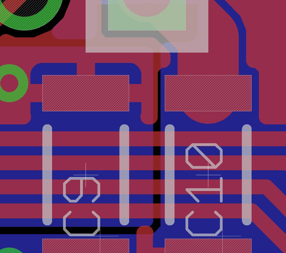
I attached an image. In the image there are two 1206 size caps. At the top of the right most cap you can see a trace that goes from a through-hole pin to the pad of the 1206. The thing I hate is how the wire, because of the thickness, overshoots the pad and there is a rounded edge sticking off the pad towards the interior of the components. Is there any way to prevent this overshoot? It looks ugly. In this case it isn't an electrical or clearance issue, but it could be in some designs.
▔▔▔▔▔▔▔▔▔▔▔▔▔▔▔▔▔▔▔▔▔▔▔▔
Timothy D. Swieter, E.I.
www.brilldea.com - Prop Blade, LED Painter, RGB LEDs, 3.0" 16:9 LCD Composite video display, eProto for SunSPOT, PropNET, PolkaDOT-51
www.tdswieter.com
939 x 832 - 91K
Comments
▔▔▔▔▔▔▔▔▔▔▔▔▔▔▔▔▔▔▔▔▔▔▔▔
Timothy D. Swieter, E.I.
www.brilldea.com - Prop Blade, LED Painter, RGB LEDs, 3.0" 16:9 LCD Composite video display, eProto for SunSPOT, PropNET, PolkaDOT-51
www.tdswieter.com
www.4pcb.com/index.php?load=content&page_id=95
▔▔▔▔▔▔▔▔▔▔▔▔▔▔▔▔▔▔▔▔▔▔▔▔
Check out my brand new site.
Mctrivia - Based on your suggestion I just tried keepout and restrict and neither one worked. I am guessing it is because keepout usually applies to copper pours and it doesn't apply with modifying wires. I tried restrict as well, but as it didn't work either. Thanks for the suggestion to check these out.
▔▔▔▔▔▔▔▔▔▔▔▔▔▔▔▔▔▔▔▔▔▔▔▔
Timothy D. Swieter, E.I.
www.brilldea.com - Prop Blade, LED Painter, RGB LEDs, 3.0" 16:9 LCD Composite video display, eProto for SunSPOT, PropNET, PolkaDOT-51
www.tdswieter.com
Just shrink the width at the end of trace. So that trace is the size you want until just after the pad starts then really small afterwards
▔▔▔▔▔▔▔▔▔▔▔▔▔▔▔▔▔▔▔▔▔▔▔▔
Check out my brand new site.
the simplest way is to remove the last trace and redraw it with the line tool. The line tool will not auto lock to the pads center like the trace tool will. the line should connect itself to the trace as long as you start where you left off on the trace. if not manualy rename.
doing this will leave a small unrouted line showing. to remove this use a really small trace(As small as your board rules will allow) to finish off to the pads center.
the harder way is to split the trace then use the resize tool to resize the last section to be really small. sounds easy but not always easy to do.
▔▔▔▔▔▔▔▔▔▔▔▔▔▔▔▔▔▔▔▔▔▔▔▔
Check out my brand new site.
Earlier today I was looking into the "cap" parameter. I believe it said round or flat. I wasn't able to change the routed wire to flat. Come to think of it I don't know that I have seen any EAGLE lines - wires or otherwise - without a rounded edge.
▔▔▔▔▔▔▔▔▔▔▔▔▔▔▔▔▔▔▔▔▔▔▔▔
Timothy D. Swieter, E.I.
www.brilldea.com - Prop Blade, LED Painter, RGB LEDs, 3.0" 16:9 LCD Composite video display, eProto for SunSPOT, PropNET, PolkaDOT-51
www.tdswieter.com