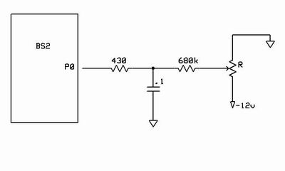
Yet another RCTIME Question
QUESTION:
Is it safe to measure a negative voltage using RCTIME?
BACKGROUND:
I found an application where RCTIME could be used to measure a voltage over 5vdc by sampling it with a 680K resistor. I was worried about the high voltage damaging the BS2 input pin but after a post here found that the current limitation of the 680k would prevent any damage. I now have that working fine. Just a couple of components and you can directly measure a 12 volt battery nicely...
It occurs to me that it would always be better to use the "RCTIME Pin, 1, variable" instruction, rather than the "RCTIME Pin, 0 variable" instruction as you get a larger range to count, therefore more accuracy. I didn't think this up, it is in the RCTIME instructions in the Basic Manual...
I did a prototype of this circuit about a week ago...

The thought is that if I have a voltage to measure ( 0 to +12vdc ) it would be better to invert it using an Op Amp to ( 0 to -10vdc ) then use the above circuit and:
High Pin
RCTIME Pin, 1, variable
instruction to read the value.
Basically, I am reading a negative voltage that ranges from 0 to -12 instead of 0 to +12.
It seems to be a much more stable way to use RCTIME as an analog to digital converter and my test has been running for several days now.
Thanks!
Greg
▔▔▔▔▔▔▔▔▔▔▔▔▔▔▔▔▔▔▔▔▔▔▔▔
AUTOMATE EVERYTHING
http://www.trainyard.net
Is it safe to measure a negative voltage using RCTIME?
BACKGROUND:
I found an application where RCTIME could be used to measure a voltage over 5vdc by sampling it with a 680K resistor. I was worried about the high voltage damaging the BS2 input pin but after a post here found that the current limitation of the 680k would prevent any damage. I now have that working fine. Just a couple of components and you can directly measure a 12 volt battery nicely...
It occurs to me that it would always be better to use the "RCTIME Pin, 1, variable" instruction, rather than the "RCTIME Pin, 0 variable" instruction as you get a larger range to count, therefore more accuracy. I didn't think this up, it is in the RCTIME instructions in the Basic Manual...
I did a prototype of this circuit about a week ago...

The thought is that if I have a voltage to measure ( 0 to +12vdc ) it would be better to invert it using an Op Amp to ( 0 to -10vdc ) then use the above circuit and:
High Pin
RCTIME Pin, 1, variable
instruction to read the value.
Basically, I am reading a negative voltage that ranges from 0 to -12 instead of 0 to +12.
It seems to be a much more stable way to use RCTIME as an analog to digital converter and my test has been running for several days now.
Thanks!
Greg
▔▔▔▔▔▔▔▔▔▔▔▔▔▔▔▔▔▔▔▔▔▔▔▔
AUTOMATE EVERYTHING
http://www.trainyard.net


Comments
▔▔▔▔▔▔▔▔▔▔▔▔▔▔▔▔▔▔▔▔▔▔▔▔
Tracy Allen
www.emesystems.com
The beauty of using RCTIME as a REAL one wire connection is that it really only uses one Stamp pin. You make a good point with the cost. I am spending $15 for a 5 in +/- 15 volt output DC to DC converter on this circuit. Inexpensive for a dc to dc converter but still 15 bucks. However, I have other stuff on the system that needs those voltages so I cannot get rid of it.
My tests show that I pretty much have an 8 bit conversion, maybe 10. But, the linearity is probably not that great. LOOKUP can fix that I am sure.
As for the Op Amp, I have yet to be able to design any A to D Converter for a micro that doesn't need some sort of Op Amp to buffer and adjust the input voltage. I always seem to need something with a knob...
Thanks for the comment.
Greg
▔▔▔▔▔▔▔▔▔▔▔▔▔▔▔▔▔▔▔▔▔▔▔▔
AUTOMATE EVERYTHING
http://www.trainyard.net