

PCB Critique
 Kal_Zakkath
Posts: 72
Kal_Zakkath
Posts: 72
After having hand-etched a few prototypes I'm now ready to step up to the big leagues and get a PCB done professionally, but figured before I shell out the money I'd chuck it up on the forum for some more experienced eyes to look over.
Here's the main things that separate this particular board from the others out there:
-All through-hole parts (easy soldering!)
-Big enough for ZIF40 connector (in case, like me, you worry about breaking pins when you try to remove the prop)
-No EEPROM on board (This way I can move the main board from project to project without having to re-program it)
-Dip switch (4) that controls:
--1. Power LED (I may want to turn it off for some battery powered projects, or if it is in an enclosure)
--2 & 3. Connects P16 and P17 for ADC to Vin (so battery level can be monitored)
--4. Bypasses the 5v regulator* (For some battery projects I am planning to run from a 6V SLA battery so shouldn't need the 5V reg)
*for safety this bypass also requires a jumper to be installed
The silkscreen still needs some additions, and I haven't decided whether or not to squeeze in space for a barrel connector but most of the grunt work is done.
Lastly, in case anyone else finds themselves in my shoes (the no-PCB-experience shoes that is) here's the main points I've come across for propeller designs:
Edit: Updated power track width after jazzed's suggestion
Post Edited (Kal_Zakkath) : 4/4/2010 8:07:36 AM GMT
Here's the main things that separate this particular board from the others out there:
-All through-hole parts (easy soldering!)
-Big enough for ZIF40 connector (in case, like me, you worry about breaking pins when you try to remove the prop)
-No EEPROM on board (This way I can move the main board from project to project without having to re-program it)
-Dip switch (4) that controls:
--1. Power LED (I may want to turn it off for some battery powered projects, or if it is in an enclosure)
--2 & 3. Connects P16 and P17 for ADC to Vin (so battery level can be monitored)
--4. Bypasses the 5v regulator* (For some battery projects I am planning to run from a 6V SLA battery so shouldn't need the 5V reg)
*for safety this bypass also requires a jumper to be installed
The silkscreen still needs some additions, and I haven't decided whether or not to squeeze in space for a barrel connector but most of the grunt work is done.
Lastly, in case anyone else finds themselves in my shoes (the no-PCB-experience shoes that is) here's the main points I've come across for propeller designs:
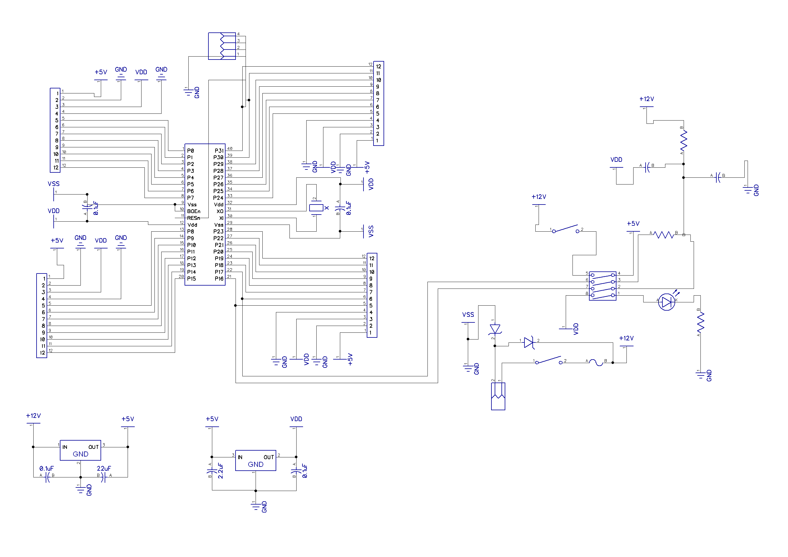
- ALL Vdd and Vss pins should be connected
- All ICs should have decoupling caps on each pair of Vdd and Vss pins - as close as possible to the pins·(I'm going with 0.1uF caps which seem fairly standard)
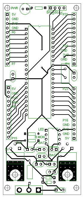
- The prop's power tracks should be the first ones laid out (i.e. they should be the shortest possible)
- Power tracks should also be thicker than data tracks (>= 0.04in·for power, I'm using 0.013in for data)
- Right-angles in tracks should be avoided (though this is probably a minor one, more applicable for high speed comms and such)
Edit: Updated power track width after jazzed's suggestion
Post Edited (Kal_Zakkath) : 4/4/2010 8:07:36 AM GMT
2673 x 1890 - 192K
283 x 657 - 25K

283 x 657 - 19K
Comments
▔▔▔▔▔▔▔▔▔▔▔▔▔▔▔▔▔▔▔▔▔▔▔▔
He died at the console of hunger and thirst.
Next day he was buried. Face down, nine edge first.
I also purchased ZIF sockets·when I got started out·of worries of bending pins...·All but the first·of them are still sitting in my parts bin, because I found them to be unnecessary. 40-pin DIPS ICs seem to be pretty durable, and you probably won't be replacing the prop unless it's damaged anyway.
If you are worried about damaging pins, you could always stack the prop on top of another standard 40-pin·socket and remove/replace prop+socket as an assembly. I used to do this with the little 18-pin PICs back when they had to be put in a UV eraser to erase them. Never bent a pin, so it was still unnecessary precaution, but it made me feel safe.
·
Your power traces should be closer to 50mil (0.05") width (>= 40mil). Why do yo have a resistor between VDD and +12V?
▔▔▔▔▔▔▔▔▔▔▔▔▔▔▔▔▔▔▔▔▔▔▔▔
May the road rise to meet you; may the sun shine on your back.
May you create something useful, even if it's just a hack.
I've gone back and forward on the EEPROM issue but still not decided yet, I suppose with SD bootloaders and such it's easy enough to change the code on-the-fly if needed.
jazzed: Thanks for that, I'll up the power trace width. Where is the resistor?
·
You should at least put a wide body SOIC SEEPROM footprint and pullup for SDA pin on your board ....
▔▔▔▔▔▔▔▔▔▔▔▔▔▔▔▔▔▔▔▔▔▔▔▔
May the road rise to meet you; may the sun shine on your back.
May you create something useful, even if it's just a hack.
Caps are both 1nF (one to GND one to 3v3), resistor from P16 to P17 is 100k, resistor to 12V (Vin) can vary but from the app note 150k is a good start.
Any EEPROM will be DIP8, in keeping with the rest of the through-hole soldering on the board (plus I think I've already got some in a box waiting for me to get the boards done)
My advice is to skip the ZIF socket altogether, it's useless but I would rather put resistors (100..220R) in the I/O lines to protect against damage and have the Prop soldered or socketed if you must. Always try to be flexible as possible in a design as you can't design for every eventuality so allow for an EEPROM on board, it costs little in time to design it in and takes very little space.
▔▔▔▔▔▔▔▔▔▔▔▔▔▔▔▔▔▔▔▔▔▔▔▔
*Peter*
I'm adding in the EEPROM now, will upload the updated version either tonight or tomorrow.
As for adding in the protecting resistors - the thought had crossed my mind, unfortunately you can't use them on video output pins (unless I'm mistaken), and I would rather not put such a limit on the board. I suppose if any chips do get fried it could be a good excuse for me to move towards the surface mount ones.
I know I was being a bit blunt in saying the ZIF is useless but that is really a very quick way of summing it up for many reasons. The resistors will probably provide more of what you need as you really don't want to keep swapping new chips in all the time, even if it is super easy. DIP ZIFs were made for quick programming of a lot of old technology EEPROM/OTP and non-ISP devices, a rapidly fading requirement these days.
I can only wonder about the +12V to switch to DIP switch and then to +5V option though, a "I knew you were messing with the switches and it's going to cost you now" provision?
▔▔▔▔▔▔▔▔▔▔▔▔▔▔▔▔▔▔▔▔▔▔▔▔
*Peter*
Peter: Yes, Vin is all I care about for the ADC (which will probably be in the range of +5.5V to 7V, not +12V), and it's only for battery charge monitoring so it doesn't have to be super accurate.
The 12V->5V switch (effectively bypassing the 5V regulator, note that it also has a jumper to help prevent it being toggled by accident) was mainly for when it is running off a 6V battery where the 5V regulator would not be needed for anything (my main project planned for this board uses only 3v3 ICs) but·the project does involve over-driving an IR LED (somewhere between 500ma-1A peaks) so I will get the power straight from the battery instead of going through the regulator first - I also figured that having the option to get Vin to the daughter boards would give more versatility if I·ever·needed it and could be ignored if I don't.
▔▔▔▔▔▔▔▔▔▔▔▔▔▔▔▔▔▔▔▔▔▔▔▔
Links to other interesting threads:
· Home of the MultiBladeProps: TriBlade,·RamBlade,·SixBlade, website
· Single Board Computer:·3 Propeller ICs·and a·TriBladeProp board (ZiCog Z80 Emulator)
· Prop Tools under Development or Completed (Index)
· Emulators: CPUs Z80 etc; Micros Altair etc;· Terminals·VT100 etc; (Index) ZiCog (Z80) , MoCog (6809)·
· Prop OS: SphinxOS·, PropDos , PropCmd··· Search the Propeller forums·(uses advanced Google search)
My cruising website is: ·www.bluemagic.biz·· MultiBlade Props: www.cluso.bluemagic.biz
You should rotate all the GND symbols that are the wrong way round, it looks rather strange the way you have done them.
I'd use a turned-pin socket instead of the ZIF socket. They are cheaper and very reliable. If you are paranoid about bending pins get a chip puller.
▔▔▔▔▔▔▔▔▔▔▔▔▔▔▔▔▔▔▔▔▔▔▔▔
Leon Heller
Amateur radio callsign: G1HSM
Post Edited (Leon) : 4/4/2010 2:28:41 PM GMT
Does that rule apply to the little surface-mount Props too? I made a board for the QFP prop with 0.025" power traces—is that not wide enough? There isn't room for anything wider.
I am seeing a large number of PLL failures with my little board, though. I wonder if it's the power traces or my usual bad luck with hardware (my own private Pauli effect).
▔▔▔▔▔▔▔▔▔▔▔▔▔▔▔▔▔▔▔▔▔▔▔▔
Links to other interesting threads:
· Home of the MultiBladeProps: TriBlade,·RamBlade,·SixBlade, website
· Single Board Computer:·3 Propeller ICs·and a·TriBladeProp board (ZiCog Z80 Emulator)
· Prop Tools under Development or Completed (Index)
· Emulators: CPUs Z80 etc; Micros Altair etc;· Terminals·VT100 etc; (Index) ZiCog (Z80) , MoCog (6809)·
· Prop OS: SphinxOS·, PropDos , PropCmd··· Search the Propeller forums·(uses advanced Google search)
My cruising website is: ·www.bluemagic.biz·· MultiBlade Props: www.cluso.bluemagic.biz
▔▔▔▔▔▔▔▔▔▔▔▔▔▔▔▔▔▔▔▔▔▔▔▔
Leon Heller
Amateur radio callsign: G1HSM
Post Edited (Leon) : 4/4/2010 4:52:17 PM GMT
I doubt there is enough difference in voltage between the Propeller pins to cause PLL failures with 0.025" traces if they are reasonable length. Bad solder joints are a more likely cause.
▔▔▔▔▔▔▔▔▔▔▔▔▔▔▔▔▔▔▔▔▔▔▔▔
May the road rise to meet you; may the sun shine on your back.
May you create something useful, even if it's just a hack.
Make the traces a little larger.
Other than that, looks good.
-Made the non-power lines thicker (0.02in)
-Made the xtal lines thicker (0.039in)
-Added 10uF bypass caps
Also fixed up the VSS/GND stuff in the schematic.
Here's the new top layout, I wont bother uploading the other two files as they have barely changed.
scotta: I'm not planning to do these ones by hand so I'll leave the pads as they are
Cluso: I realise the need for the EEPROM, my original idea was to have the EEPROM on one of the daughter boards so that I can just unplug one board, plug in another and off I go without any reprogramming - but after reconsidering the EEPROM will now be on-board and I'll use the SD bootloader to acheive the same effect.
Should I also put a ground ring around my xtal? or will the ground plane underneath suffice?
I have a bootloader for the RamBlade that does what you want. Works great and only relies on fixed pins for the SD card (changeable in the con of the code), so just recompile it.
▔▔▔▔▔▔▔▔▔▔▔▔▔▔▔▔▔▔▔▔▔▔▔▔
Links to other interesting threads:
· Home of the MultiBladeProps: TriBlade,·RamBlade,·SixBlade, website
· Single Board Computer:·3 Propeller ICs·and a·TriBladeProp board (ZiCog Z80 Emulator)
· Prop Tools under Development or Completed (Index)
· Emulators: CPUs Z80 etc; Micros Altair etc;· Terminals·VT100 etc; (Index) ZiCog (Z80) , MoCog (6809)·
· Prop OS: SphinxOS·, PropDos , PropCmd··· Search the Propeller forums·(uses advanced Google search)
My cruising website is: ·www.bluemagic.biz·· MultiBlade Props: www.cluso.bluemagic.biz
Cluso: Hopefully I understood what you meant about the ground loop around the xtal - why did you say to use a via instead of going to the prop's VSS pin? just curious.
Also managed to shrink the board down a bit to 4.3" (109.2mm) so hopefully it's small enough to *just* fit in a 111mm project box.