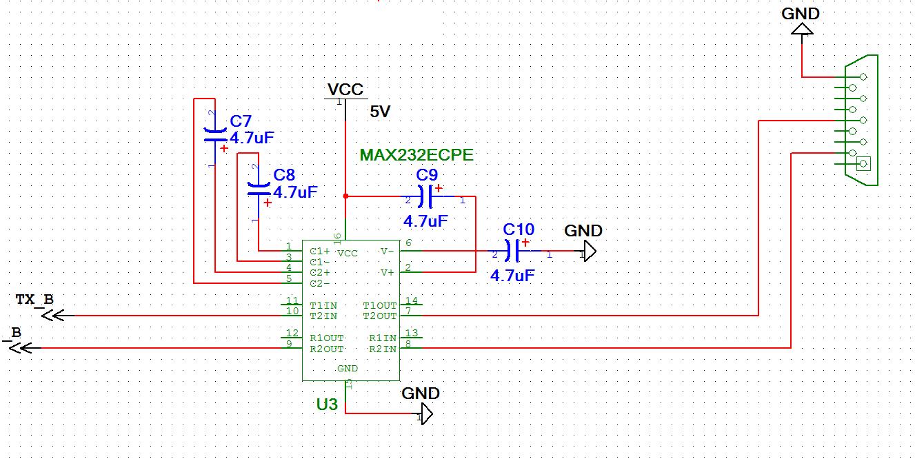
Prop to MAX232 into another MAX232
I was wondering if any one has used the propeller with a max232 ic and a male DB 9 connector. I have always used a max232 to receive data from a computer, but now I drew up a circuit that sends data through a max 232 (using the propeller) to a device that also uses a max232.Its not working correctly and wanted to know if anyone has a suggestion. Attached is the schematic of the max 232 chip that connects to the propeller.
Thanks
Thanks


Comments
The Propeller Professional Development Board (PPDB) has a MAX3232 and a DB9 connector. Have a look at the schematic and manual for it.
For a D9 3 wire connection, use pins 2,3 and 5.
I remember a simple rule - male D9s output on pin 3. From that you can conclude that females output on pin 2. Pin 5 is always ground. Ignore the rest. Generally a PC has a male D9 (real D9 on the back, or a USB to D9 cable off ebay for $2). So this will go into a female D9 on pin 3. Which should then go into either pin 13 or pin 8 of the max232. Yours goes into pin 7 which is an output.
Unless you are outputting to another device?
I think you are very close. Maybe it is just the series resistors as mentioned above.
Also another rule of thumb - all RS232 signals are 'resting' at negative volts, eg -9V or -12V. But the TTL equivalent of 'resting' is 5V. (3V on the propeller). So you should be able to trace through a resting signal
+3V on the prop => -9V RS232 => wire => max232 at the other end => +5V => 1k resistor => 3V on a propeller.
See my link below - that takes you to a page with a schematic showing a max232 to implement two serial ports on a prop.
▔▔▔▔▔▔▔▔▔▔▔▔▔▔▔▔▔▔▔▔▔▔▔▔
www.smarthome.viviti.com/propeller
▔▔▔▔▔▔▔▔▔▔▔▔▔▔▔▔▔▔▔▔▔▔▔▔
Leon Heller
Amateur radio callsign: G1HSM
I believe this is another way of saying what Dr_Acula is describing.
▔▔▔▔▔▔▔▔▔▔▔▔▔▔▔▔▔▔▔▔▔▔▔▔
John R.
Click here to see my Nomad Build Log
That rule of thumb works. Thank everyone for the help. So to conclude I put a 4K resistor in between the propeller and the max 232. And I had to re wire the pins as Dr_Acula mentioned.
Thanks all