Shop OBEX P1 Docs P2 Docs Learn Events
Adjustable Current Sensing — Parallax Forums

Adjustable Current Sensing

T ChapT Chap Posts: 4,223
edited 2010-04-09 11:04 in General Discussion
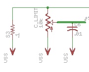
Can someone suggest a better way to do this? I want to use a multi turn pot to adjust the trip point to the +sense input of a 3phase motor driver. The input trips at 100mv volts. In the photo, there is a .1 sense resistor off the low side of the mosfets to the motor. The wiper off the 10k trim pot goes to the driver IC +sense input. My hope was the the voltage would just divide using the pot, and I could set a threshold manually. The way it works out though is that there is no real adjustment, the trim pot is more of an on or off switch, you turn the screw and it finds a thin sweet spot where it toggles the input. What I need is a way to really adjust the voltage level and find the place that makes sense for the application where it should trip. Any suggestions for solving this?

Post Edited (Todd Chapman) : 3/26/2010 6:17:15 PM GMT
180 x 146 - 8K

Comments

  • stamptrolstamptrol Posts: 1,731
    edited 2010-03-26 19:04
    How big is the motor? With 1A flowing in the sense resistor, you'll hit 100 mV very easily and the 10K pot will be at its lower end of travel. If your desired trip point is at a higher current, the twitchiness will be greater. You may get more statbility with a bit more capacitance as well.

    Also, I assume there are a set of mosfets in a 3 phase bridge arrangement, switched with some sort of PWM scheme. Can you show a schematic of the drive?

    Many commercial units actually measure DC current going into the inverter section so that there is a steadier flow of current compared to measuring one of the phases.

    ▔▔▔▔▔▔▔▔▔▔▔▔▔▔▔▔▔▔▔▔▔▔▔▔
    Tom Sisk

    http://www.siskconsult.com
    ·
  • T ChapT Chap Posts: 4,223
    edited 2010-03-26 19:56
    Thanks for that info. The driver IC feeds another chip that actually fires the 3 high and 3 low irf540's. There several motor sizes that get used, so a variable solution is required. It is true that the 10k is turned way down like you said. I only need around 2 amps, and the motors are causing too much voltage on the input without some scaling. Seems the 10k divider is not the right idea though. I will post the full schematic later.
  • James NewmanJames Newman Posts: 133
    edited 2010-04-07 03:38
    Use an opamp. There are a few ways you could do it, but the first that comes to mind is to amplify the current sense voltage, and use a pot on the opamp feedback to adjust the gain.
  • T ChapT Chap Posts: 4,223
    edited 2010-04-09 07:38
    The 10k from the old tests had no real sweep from too much to too little limiting, it just jumped from one to the other. Today I got some 300ohm and 1k single turn trim pots. The 1k worked quite nicely, you could find a good spot for where you want the limiting to start over the course of travel with plenty of flexibility between the extremes. I also changed the cap to .1uf. Thanks for the suggestions above.

    Post Edited (Todd Chapman) : 4/9/2010 3:43:50 PM GMT
  • daniel.jashuadaniel.jashua Posts: 1
    edited 2010-04-09 11:04
    THANKS for the useful posting..!

    .

    ▔▔▔▔▔▔▔▔▔▔▔▔▔▔▔▔▔▔▔▔▔▔▔▔
    nametag holder
Sign In or Register to comment.