

Multiple LEDs, Transistors, SX28
 John Couture
Posts: 370
John Couture
Posts: 370
I am obviously missing a fundamental about transistors.
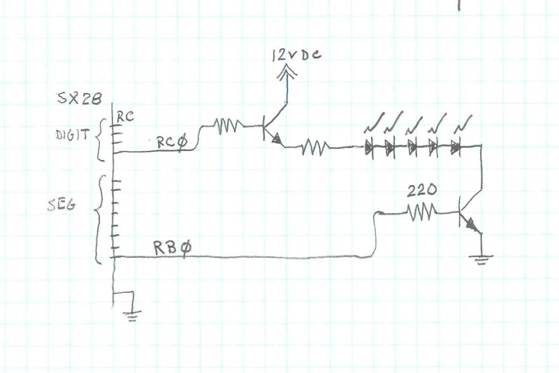
I have a four digit sign (i.e. a clock).· Each digit is seven segments. Each segment is 4 or 5 LED's.· Thus the max voltage drop is 8.4v.· My supply voltage is 12V.
Segments are controlled using RB to switch the cathode side of the segment.
Digits are controlled using RC to switch the anode side.
I can switch the segments ok (RB) by using 2N3904 (npn) transistors connected to the RB pins on the SX28.
I can't seem to figure out how to switch the anode side because I am switching 12V and need to protect the SX28 from that 12V.
Attached is a schematic of attempt # 3,281 (seemingly) of trying to get this to work.
My gut tells me I have to figure out how to "buffer".· I have at my disposal an unlimited number of PNP or NPN transistors along with a good supply of ULN2803 IC's (yea, I've tried them all but can't seem to get the right combination).· I've tried the Darlington Pair but, again, I think I'm missing something.
I was trying to avoid having to use 7407's (high current buffers) because I would have to order them and would like to use what is on hand.
▔▔▔▔▔▔▔▔▔▔▔▔▔▔▔▔▔▔▔▔▔▔▔▔
John J. Couture
San Diego Miramar College
800 x 534 - 34K
Comments
So, OK, here's what then... (see attached.)
▔▔▔▔▔▔▔▔▔▔▔▔▔▔▔▔▔▔▔▔▔▔▔▔
John J. Couture
San Diego Miramar College
Basically all the program does is count up from zero to 9999 and display the number on a four inch LED panel.·
Each segment of the panel is 4 or five LEDs in series so you can't just drive it from an MCU, you have to use transistors or a driver chip.· In this case I used several transistors (schematic attached).
Pictures of Prof Dev Board and Panel
▔▔▔▔▔▔▔▔▔▔▔▔▔▔▔▔▔▔▔▔▔▔▔▔
John J. Couture
San Diego Miramar College
Post Edited (John Couture) : 3/31/2010 3:40:33 PM GMT