

Noob Help?
 Scope
Posts: 417
Scope
Posts: 417
Hello,
I'm new to schematics, fairly new to microcontrollers.
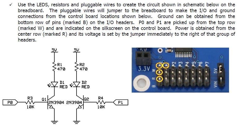
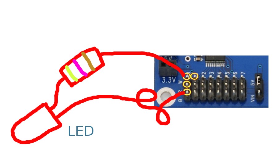
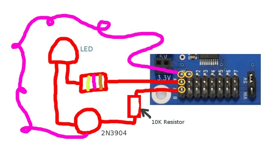
Would the image on the left (from the Stingray book) work as shown in the image in the middle or do I need to add the 2N3904 transistor as I've shown in the right image?
I'm a little confused (and embarrassed) about the 2N3904 transistor - is that part of what's on the Propeller Robot Control Board or do I need to add it to the circuit used to create to test the Propeller Robot Control Board?
And yeah, I realize I probably need to learn more of the basics before embarking on the Propeller Robot Control Board.
Thanks,
Scope
Post Edited (Scope) : 3/21/2010 12:18:26 PM GMT
I'm new to schematics, fairly new to microcontrollers.
Would the image on the left (from the Stingray book) work as shown in the image in the middle or do I need to add the 2N3904 transistor as I've shown in the right image?
I'm a little confused (and embarrassed) about the 2N3904 transistor - is that part of what's on the Propeller Robot Control Board or do I need to add it to the circuit used to create to test the Propeller Robot Control Board?
And yeah, I realize I probably need to learn more of the basics before embarking on the Propeller Robot Control Board.
Thanks,
Scope
Post Edited (Scope) : 3/21/2010 12:18:26 PM GMT
Comments
With the 2n3904, you use significantly less current from the microcontroller to turn on the LED.
There is a 10,000 ohm current limiting resistor. In this setting the LED gets power from another source while the Propeller merely provides control.
With the LED directly driving at 3.3volts, the microcontroller is providing quite a bit more current to the LED.
The usual value of the current limiting resistor varies between 470ohm and 220ohm. Variations are commonly due to using different color LEDs and whether full on or a blinking condition is chosen.
The real issue is how much current can the microcontroller safely provide? Opinions vary from 15ma to 25ma per pin depending on the manufacturer. (Parallax tends to make more robust microcontrollers that can tolerate 25ma, but that doesn't mean you should use 25ma when as little a 0.5ma will do the job. And there is also a total power limitation for the whole microcontroller and if you run all pins at 25ma, you may destroy the microcontroller even though each individual pin is considered safe.
In other words, if you are driving LEDs with all the pins and full on, the 2n3904 transistor might be a very good idea. But if you are merely driving one LED and intermittently (while all the other pins are not being used), the lack of a transistor is no big deal. It is all about protecting the microcontroller from excessive power demands which created the heat that destroys one. Consider the fact that very very fine gold wires are providing that 25ma inside the IC package and even smaller transistors and FETs are handling the power loads.
So you see, the Propeller Robot Control Board took the more conservative approach and provided maximum protection to the Propeller chip.
You question is certainly not stupid or naive. This is one of the first and most important issues of designing circuits as it does no good to place excessive demands for power on any component. The results are destructive and in some cases (with higher voltages and higher amperage) can be very dangerous.
▔▔▔▔▔▔▔▔▔▔▔▔▔▔▔▔▔▔▔▔▔▔▔▔
Ain't gadetry a wonderful thing?
aka G. Herzog [noparse][[/noparse] 黃鶴 ] in Taiwan
Post Edited (Loopy Byteloose) : 3/20/2010 4:39:26 AM GMT
As a matter of fact, I am considered to be quite bright, however I NEVER get the most simple basic stuff for some reason? (I get the complex stuff.)
For example I was reading an automotive repair book and it kept referring to the "MT" model car. I looked all over for what in the heck MT stood for!
It turned out it was the "Manual Transmission" model....
Anyway every time I ask a question, I've learned there is *always* someone else wanting to know the same thing.
Rich H
▔▔▔▔▔▔▔▔▔▔▔▔▔▔▔▔▔▔▔▔▔▔▔▔
The Simple Servo Tester, a kit from Gadget Gangster.
Fixed it - thanks.