

raw rf, hope lost?
 curseofthedonkey
Posts: 11
curseofthedonkey
Posts: 11
I've been messing around with this almost every spare moment I could manage to get to my workroom.
Objective: Transmit a decimal. That's it, just one stinkin' number consistently. I'm getting noise, and the value of x IS changing with that noise. Should I just pack up these cheapo raw RF modules and go ahead with XBee or can I confidently say I've done everything I can? I posted before, and Dr_Acula and Mike Green were very helpful with some great tips (feel free to give more ) . I've simplified the code and started using the bs2 library to TRY to get this working. No luck. The headphones are a great help in "audio debugging".
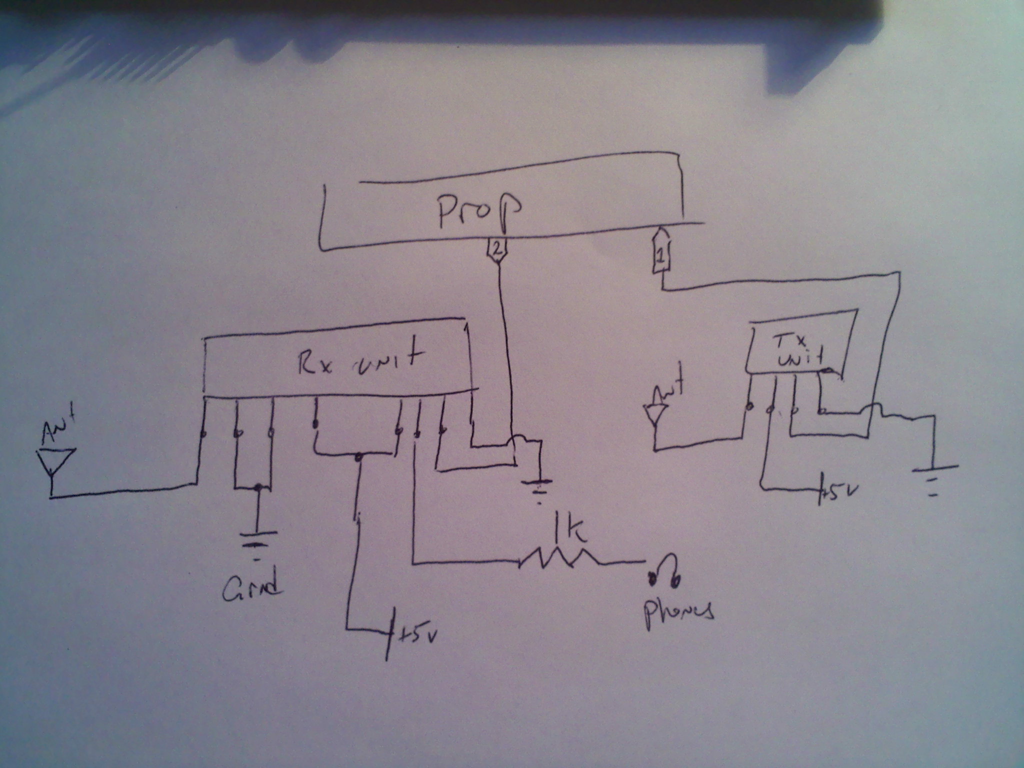
I've attached a terrible drawing of the schematic, but I'm using two pins from the same prop on the same breadboard.
Here's the code. Notes below.
If I change the DEC value (it's 24 here) I get different reactions on the Parallax Serial Terminal. All nonsense, but different characters on the terminal, sometimes tones, and sometimes nothing at all. I found that strange. Antennas help with the static, but I get the same results as if I weren't using them.
Anyway, I have every thing running separately to keep it as simple as possible. If anyone has any insight to this it would be very helpful. If these RF modules just aren't doing what they're supposed to do, that would be nice to know too.
Objective: Transmit a decimal. That's it, just one stinkin' number consistently. I'm getting noise, and the value of x IS changing with that noise. Should I just pack up these cheapo raw RF modules and go ahead with XBee or can I confidently say I've done everything I can? I posted before, and Dr_Acula and Mike Green were very helpful with some great tips (feel free to give more
) . I've simplified the code and started using the bs2 library to TRY to get this working. No luck. The headphones are a great help in "audio debugging".I've attached a terrible drawing of the schematic, but I'm using two pins from the same prop on the same breadboard.
Here's the code. Notes below.
CON

_clkmode = xtal1 + pll16x                        ' 5 MHz crystal  80 MHz system clock
_xinfreq = 5_000_000

VAR

long stack[noparse][[/noparse]20]
long stack2[noparse][[/noparse]20]
byte x

OBJ

bs2 : "BS2_Functions"
debug: "FullDuplexSerial"


PUB transmit
dira~~
outa:=1


cognew(receive, @stack)                              'start receiving
cognew(print, @stack2)                               'start printing

debug.start(31,30, 0, 2400)                         'start full duplex serial

repeat
  bs2.SEROUT_DEC(1, 24, 2400, BS2#Inv, 8)          ' send dec(24) on pin @2400Baud, mode 0, 8 bits


PUB receive


repeat
   x:= bs2.SERIN_DEC(2, 2400, BS2#NInv, 8)          'receive char "A" on pin, mode 1
   'waitcnt(clkfreq + cnt)                          'uncommenting this line allows a tone to come through, yet displays nothing.

PUB print

repeat
  debug.dec(x)                                       'print
 waitcnt(clkfreq +cnt)
If I change the DEC value (it's 24 here) I get different reactions on the Parallax Serial Terminal. All nonsense, but different characters on the terminal, sometimes tones, and sometimes nothing at all. I found that strange. Antennas help with the static, but I get the same results as if I weren't using them.
Anyway, I have every thing running separately to keep it as simple as possible. If anyone has any insight to this it would be very helpful. If these RF modules just aren't doing what they're supposed to do, that would be nice to know too.
2048 x 1536 - 357K
Comments
Could you extend the wiring to one and get a few yards between them.
▔▔▔▔▔▔▔▔▔▔▔▔▔▔▔▔▔▔▔▔▔▔▔▔
Style and grace : Nil point
Post Edited (Toby Seckshund) : 3/19/2010 7:39:30 PM GMT
▔▔▔▔▔▔▔▔▔▔▔▔▔▔▔▔▔▔▔▔▔▔▔▔
Leon Heller
Amateur radio callsign: G1HSM
▔▔▔▔▔▔▔▔▔▔▔▔▔▔▔▔▔▔▔▔▔▔▔▔
Style and grace : Nil point
Thanks for the tips. It's research time. I'll report back after a few more configurations.
the component bits of that number are 16 + 8 which are next to each other. So you have a simple waveform of low, low, low, high, high, low, low, low (or it's inverse) MSB first.
This presents a low bandwidth to be transmitted/received. 170(dec) would give high, low, high, low .....and present a worse case.
Do you have access to a 'scope ?
EDIT
Also, the Prop might be chucking out all sorts of interferance, if you were to extend the wiring to one of the modules then I would get the Rx away from the Tx and the Prop. The cheaper ones are regenerative and open as a barn door.
▔▔▔▔▔▔▔▔▔▔▔▔▔▔▔▔▔▔▔▔▔▔▔▔
Style and grace : Nil point
Post Edited (Toby Seckshund) : 3/19/2010 9:10:18 PM GMT
It may be a couple days before I get the opportunity, but at first chance I'm going to try getting the receiver away from the whole board. I'll repost then.
In the mean time I will be reading on up Manchester code and decoding. There has already been a few discussions about it.
About 6 hours ago I was just happy to see something showing up on the terminal...on to the next.
Thanks again. I'll be sure to provide an update as soon as I have one.
Good luck
▔▔▔▔▔▔▔▔▔▔▔▔▔▔▔▔▔▔▔▔▔▔▔▔
Style and grace : Nil point
First - on that schematic, I see 5V on the Rx and that is going directly into the prop. ? needs a 1k series there.
Also - I'm presuming the Tx is ok with 3V3 as high. It probably is, but you can't really be sure unless you send a tone into the Tx and see a nice squarewave on a scope on the Rx. Speaking of scopes, they are very handy, but if you spent the same money on transceiver modules you could buy quite a few and you wouldn't need the scope!
What is the antenna length?
And yes, any closer than 1 metre and these modules interfere.
Any chance of a photo of the setup - the schematic shows the important bits, but it is sometimes the unexciting bits like bypass capacitors that make the difference between failure and success.
I have to confess, despite being able to transfer files between propellers I still don't understand Spin. When you say
does that not repeat endlessly and never get to the next line, which is the receive part?
After two years of discussions on the picaxe forum, I think I can state categorically that sending single bytes does not work. You need a wakeup packet of at least six ascii U (which is 01010101 in binary). Then a start preamble, eg ABC. Then the bytes. And then a checksum at the end.
This is where the transceiver modules are so much better, because you can send one byte in and one byte comes out the other end. With raw RF, everything has to be wrapped up in a packet.
The serin part needs to be polling round and round looking for A, then if that comes in, B and C and only then does it go off and get the rest of the bytes. Otherwise it goes back to polling looking for an A.
And you might need a timeout.
I've used manchester coding but it hasn't been necessary to get this working and it only added a tiny (5%) distance to the maximum range. But it halved the data rate.
▔▔▔▔▔▔▔▔▔▔▔▔▔▔▔▔▔▔▔▔▔▔▔▔
www.smarthome.viviti.com/propeller
Thanks for the reply. There must be a very good reason I'm not seeing a simplified raw rf txrx object. I can only assume this is because it is not simple at all. This began as a simple plan to connect serially via rf with some cheap modules. As you can see it's become a complex task to transmit even a byte of data accurately, or at all. This is mainly an exploratory project, a proof of concept, as I have had no prior experience with wireless ventures.
My circuit building could use a little work too. I'll try and get you a good pic soon, I have more access to computers than I do my board.
TX 3.3 volt high: I get a tone on the headphones, however I have not been able to accurately measure anything at all due to the lack of a scope. Again, I've learned my lesson.
Antenna: 1 foot each. Just some hookup wire.
repeat code: YES. The constant repeat of the transmission is an attempt to net a valid return value. I don't know if this is effective, but it was the best I had to go on. The following code is meant to receive this information as var x. I have them running on separate cogs:
I did this so I might have a better chance of at least returning the correct decimal. Even once out of 100 would be a major accomplishment, then I had hoped to narrow down the actions for error checking. If this was a ludicrous thought process to someone who may know more about this stuff I understand. It was the most obvious method to attempt, but without any usable return value at all, it proves greatly inadequate.
If you look at the dracblade thread on the last post is a screen grab of two propellers talking to each other wirelessly. This has taken 2 years to get to this point.
One day I'd like to get the raw modules into the network - if only because
a) I think the prop has enough onboard smarts to handle them and
b) they are so much cheaper.
What I'm not sure is how the serial object code works at the assembly level. I think they will work properly, but it isn't how they work, it is how they fail. So if somehow there is what is called a framing error, and you are sending a start bit and then 8 data bits and then a stop bit and then a tiny delay, but somehow the serial port object has decided to start reading in the middle of the byte, it will still (I think) read out bytes as if they are valid bytes.
I think this is what might be happening with the raw rf modules - they start off listening to static, along comes a byte but they probably start reading in the middle of the byte rather than the beginning. So you will then get a series of repeating data but it wont be the right data.
The ABC header on picaxes exploits some internal code inside a picaxe that captures those header bytes reliably and also synchronises things for the next bytes. I'm not sure such a thing has been written for the propeller.
So - a general question - how do you detect and get out of framing errors?
The picaxe solution has been to add small delays of definite zero - ie zero.... then UUUUUU then ABC then the data
And some people on that forum feel very strongly about adding a delay between UUU and ABC as well.
What I'm not sure about is whether to plug raw rf modules into existing serial objects, or whether to go back to basics with the bell modem obex (which I don't think will work, as the bell obex uses sine waves and the raw rf modules work with square waves). I think the answer is some smarter ways to talk to the serial objects - and I think it might involve delays
eg delay - send UUUUU delay send ABC etc
The delays need to be just the right length. Too long and the centrepoint for the Rf Rx will drift. Too short and framing errors can't be detected. I am guessing the right delay is about one and a half byte lengths. eg about 15 bit lengths. So if you are 2400 baud, 15/2400th of a second. I'd be hoping that would allow a framing error to be detected.
▔▔▔▔▔▔▔▔▔▔▔▔▔▔▔▔▔▔▔▔▔▔▔▔
www.smarthome.viviti.com/propeller
▔▔▔▔▔▔▔▔▔▔▔▔▔▔▔▔▔▔▔▔▔▔▔▔
Style and grace : Nil point
http://www.sparkfun.com/commerce/product_info.php?products_id=8946
http://www.sparkfun.com/commerce/product_info.php?products_id=8950
First order of business will be to separate the modules by at least a couple meters.
I'll be sure to post an update.
▔▔▔▔▔▔▔▔▔▔▔▔▔▔▔▔▔▔▔▔▔▔▔▔
Leon Heller
Amateur radio callsign: G1HSM
Post Edited (Leon) : 3/20/2010 12:10:33 PM GMT
No, raw rf is a way of describing a range of modules. They are generally under $5, the Tx and Rx are seperate (not a 'transceiver'), they have Rx sensitivies around -93 to 103db, they don't have antennas included (you have to add the wire), and, most importantly they output random white noise if nothing is transmitting nearby. There are many different brands and manufacturers. Some are only $2, hence the motivation to get them working!
They are much more complicated to interface than 'transceiver' modules. Transceiver modules generally are $15 to $25 each, have an onboard micro, can do TTL or RS232 signal levels or both, when there is no data being transmitted the output is zero or 5V, they are a lot more sensitive (around 100 to 1000 times more), they have a screw connection for an antenna, and they are generally a drop-in replacement for a wired connection.
Raw RF modules are harder to get working. I think they are going to need some spin code that couples with existing serial code. I am not surprised at the comments on the sparkfun page, as these modules are often advertised as "data in = data out" and that is precisely what they do not do. However, I have managed to send data over 500 metres with modules very similar to these using picaxe chips.
I think what is needed is another layer of code that interprets data coming in. It is in a loop looking for valid U characters, then if that arrives it looks for a header, and if that arrives it looks for a data byte(s), and if that equals a checksum then, and only then, does it output to a circular buffer. From the users point of view, you want an object where you ask if a byte is in the buffer, just like with serial data objects. You might also want some data statistics saying 'I'm getting the header bytes ok but only half the checksums are correct".
I really do think this is just a combination of delays and existing serial code. But I need to understand something more fundamental first - how can you run background spin code? I understand running cog code independently, and I understand running the 'main' cog which is interpreting the main spin program. I'd like to know if you can run other spin code in parallel? OR - is it going to be necessary to build a brand new pasm object to do this - an object based around the serial object but with some code doing the above data checking and necessary delays.
▔▔▔▔▔▔▔▔▔▔▔▔▔▔▔▔▔▔▔▔▔▔▔▔
www.smarthome.viviti.com/propeller
www.rfsolutions.co.uk/acatalog/Smart_Radio_433_Transceiver_Module.html
▔▔▔▔▔▔▔▔▔▔▔▔▔▔▔▔▔▔▔▔▔▔▔▔
Leon Heller
Amateur radio callsign: G1HSM
I had put a crude form of squelch on the one I used to shut it up on no carrier
And another thing ... The antenna for 433 should be about 7" (17cm) long.
▔▔▔▔▔▔▔▔▔▔▔▔▔▔▔▔▔▔▔▔▔▔▔▔
Style and grace : Nil point
RF is·an unpredictable environment - I can't imagine trying to make it work without a scope. I'm impressed!
Jim-
▔▔▔▔▔▔▔▔▔▔▔▔▔▔▔▔▔▔▔▔▔▔▔▔
Signature space for rent!
Send $1 to CannibalRobotics.com.
I have been pondering Leon's comment about Manchester encoding and I think this has a lot of merit. Consider - 6 U characters, one or two pauses, a unique wakeup byte combination (2 or 3) and a checksum, all to send one data byte.
I think Leon is right about Manchester coding.
Thinking about this more, it really needs to be pasm and to behave like the existing objects - ie complicated behind the scenes but easy to use.
I think there will always be a need to synchronise somehow, even with Manchester coding. So the Rx is receiving white noise and a tone appears which is the wakeup byte at clock frequency f (eg 4800hz) transmitted as the translated byte 0x00 to a Manchester code. en.wikipedia.org/wiki/Manchester_code Then you might send 0x55 as the next byte and this ends up being a tone of f/2 and the receiver is expecting this transition so it can use that to synchronise the start of the bytes. Then just send the packet.
One of the things about the picaxe system with lots of U bytes and only a few data bytes is that the picaxe can only handle a maximum of 14 byte packets. So you can get away with a few data bytes being 0x00 0x00 0x00 and it won't shift the balance too much. But with longer packets (which the prop can handle) then it makes a lot more sense to send via Manchester encoding. (with the picaxe and long packets some have used a 'poor amn's' Manchester, ie send bytes in pairs and if you send 0x01 then send 0xFE straight afterwards (255-n).
So - this needs to be a pasm object. It uses one pin for Rx and one for Tx. Asynchronous. Buffered (? up to 256 bytes if possible). Maybe even add the fancy system used in the transceiver modules where if you send one byte it waits for more bytes and IF (buffer full OR >30 milliseconds) THEN clear buffer. That way the bytes end up in packets.
On the Rx end take the packets and translate back to bytes and put them in the rx buffer ready for spin to collect them.
Hmm. Complicated to write. Big benefits down the track as RF comms for under $5.
▔▔▔▔▔▔▔▔▔▔▔▔▔▔▔▔▔▔▔▔▔▔▔▔
www.smarthome.viviti.com/propeller
Nope. Not Lynx. Generic rx tx modules that were under five bucks from sparkfun (rx module: MO-RX3400-A from Holy Stone Enterprise Co and corresponding tx module). No scope either, but that wasn't an intent to make it even more challenging. Just plain unpreparedness on my part. Frustrating to say the least, but it does make me chuckle a little to know that my first week of delving into wireless transmission has already provided me with a worthy nemesis.
This has turned into a rather interesting and much more challenging project than I had thought. This was a small piece to a larger project, and while I may just move forward with an XBee for the main one, I now have two main projects I'll be working on that will keep me busy for a while.
I'll continue to work on this and will post updates. Thanks to everyone for the helpful advice!