

Troubleshooting QTI Infrared sensor in digital mode
 WHall
Posts: 22
WHall
Posts: 22
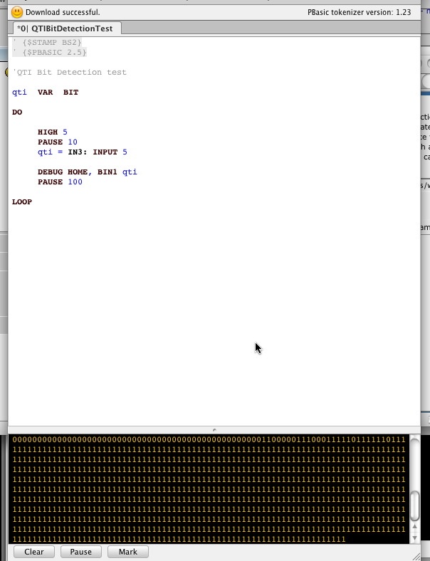
I could use some help on using the QTI sensor in digital mode. Attached are a couple of screen shots of the circuitry and the code I'm using. I can get digital output, but there doesn't seem to be any rhyme nor reason to it. I've tried various objects at various distances, including a printed out wheel encoder in black and white, but to no avail. Ideally, I want to rotate the wheel in front of the sensor and get either a "one" or "zero".
Out of the box, I was able to use the sensor in analog mode to debug IR "time" using RCTIME. But since trying to convert it, I can't get it to recognize black and white surfaces in digital mode with any certainty that the number corresponds to the object it is sensing.
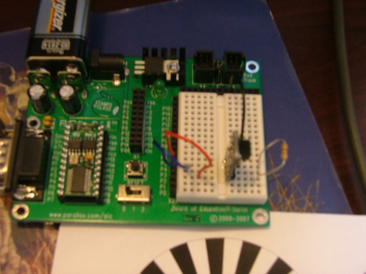
The resistor in the picture is 10 ohm. P5 is connected to "W" and P3 is connected to "R". "B" goes to VSS.
I'm casting myself on the mercy of the forum members. Is the circuitry and code correct? Thanks for any and all help!
Out of the box, I was able to use the sensor in analog mode to debug IR "time" using RCTIME. But since trying to convert it, I can't get it to recognize black and white surfaces in digital mode with any certainty that the number corresponds to the object it is sensing.
The resistor in the picture is 10 ohm. P5 is connected to "W" and P3 is connected to "R". "B" goes to VSS.
I'm casting myself on the mercy of the forum members. Is the circuitry and code correct? Thanks for any and all help!
1280 x 960 - 897K
604 x 788 - 117K
Comments
There is a document for the BOEBOT that shows how it's done but did not find it.
Maybe it should be referenced on the product page.
EDIT:
OK I did a little digging on this and found some interesting things.
When I ordered my line follower Appkit for the Boe-Bot (#28108) I also downloaded the docs. It was v1.1 8/10/2007. Just went looking and the doc has been revised. What got revised? Well the section where they describe converting it into a digital sensor has been completely removed. The funny thing is that the 10k resistors (part#150-10030) used for that purpose are still included with the newer kits if you are to go by the kit contents.
So it looks like a 10k between the W and R of the QTI is what Parallax recommended but why they removed it in the docs·is a mystery.
Post Edited (Propability) : 3/16/2010 10:36:28 PM GMT
From what I see the QTI being driven from an IO pin would be for power saving and not really a necessity if you are not worried about battery consumption.
What I have done is power the QTI from Vdd (the W pin of the QTI is the power pin not the signal pin -why did they do that?).
The B pin of the QTI to Vss(ground).
The R pin of the QTI to a stamp pin for both output and input (for rctime measurement).
To make it flexible I also have the R pin hooked up to another stamp pin thru(in series) a
10k resistor.
That way I can I can still do rctime by disabling the pin that is hooked up to the resistor but I can also do digital by setting that pin high .
Hope this helps.