

Stereo TSL1401
 rjo_
Posts: 1,825
rjo_
Posts: 1,825
Hi guys,
It's been a while since I have posted an update on this project.·
2 steps·backward... one step forward.
I have completely redesigned the camera, from the ground up.· Software still sucks, but I did solve my acquisition issues[noparse]:)[/noparse]
I cut down two protoboards, built a miniSD card adapter, etc. etc.
I am just about ready to hook up the·sensors and try out the new design.· I am really struggling with moving·it around...·decided to make my own pan and tilt... which is probably a mistake.· I've wasted an inordinate·amount of time on the mechanical issues.··We'll see.
Rich
1600 x 512 - 106K
Comments
This is great !
Stereo vision.
Please share more about this !
Is there a thread that I missed ?
I am very excited about this application for the reason that I was hoping to add something like this to my spy-bot with laser range finding capability in the future.
More pic's please!
Any schematic's ?
Robbie
Thanks... I think the documentation is as important as the soldering: So, I am intending to do it all the ight way and post it here.
I have posted a couple of notes about this... always with the added disclaimer that I am in the process of changing everything and as soon as I get it stable, I'll be posting all of the details.
I have now build everything about three times and am getting close to finalizing it... but then again, I was close about a month ago and then decided to tear it all apart and do it again[noparse]:)[/noparse]
ILMP (I love my Propeller[noparse]:)[/noparse]
Rich
That would be great to post it here.
Can't wait to see the finished project !
Building projects several times is something I think most of us do.
You are never satisfied with it or improving your idea is always done to make it somewhat perfect in your own eye's.
I'm a hardware guy at heart.
I know exactly how you feel !
Software is well, let's say I would rather ask someone to do it for me, I'll take care of the hardware.
With Parallax, I am learning.
You'll know exactly what I mean when I detail my approach to hardware... it is even worse than my software ... but it will work... for a few minutes at a time.
I'll do my best to get the nitty gritty posted in the next couple of days. It would be a blast to have you look at it and say... "you know Rich, if you would just...."
Rich
When I want a small Propeller board I use one of these.· Wire up a place for a prop plug, add a crystal, eeprom, a couple of caps and you're good to go (assuming you have 3.3V handy).· The TQFP chips aren't too bad to solder.
If any of you reading this are afraid to solder surface mount parts, read the tutorial at SparkFun.· I was amazed how easy it was.
Duane
Edit: By the way cool project.· I'll be watching for updates.
I will post diagrams later.· Sorry about the delay.
Stereo_TSL1401_mcp3208_rjo_003 controls and displays output from two tsl1401 line scanners with a single Prop(camera Prop).
Stereo_TSL_UI_rjo_002 runs on a second Prop(UI Prop) and stores data from the stereo camera to a uSD card.
In the next iteration, the UI prop will also control an additional stereo camera, and the pan and tilt.
In this version, acquisitions are stored to a uSD card when a trigger button attached to· Pin 1 of Camera Prop is pushed.
Acquisition storage is indicated by an LED attached to pin 3 of the Camera Prop.
Hardware:
+3.3 Volts everywhere.
Aside from 1k resistors on data lines, there is a single transistor(TIP120), with base connected to the Propeller Pin 9 for SI signal to TSL1401.· This transistor switches VDD to SI
and drives output to the SI pins of the TSL1401.·· For additional setup info of the TSL and MCP units,· see device data sheet and documentation
in the Parallax store.· Additional diagrams will be posted to the this thread.
Knobs... a knob is used to set windowing of pixel values.· This knob consists of a 1K pot· connected to VDD. Output is tied to ground with
a 1.5K resistor and fed into MCP3208 channel 2.
PERFORMANCE:· With this code there is a time step resolution for the integration period of 5.6usec.· Minimum integration period is 44.8 usec.··· The integration period is set through the "TIP" variable.· Presently this value is set in the ParamInit method.· The TSL1401 is capable of better performance.· And with more clever programming, the Prop can easily drive the TSL1401 at its theoretical maximums.
With this implementation, the Prop is driving two TSL1401s with a combined (burst) pixel rate of approximately 2.5M Pixels per second.
Of course effective acquisition rates are governed by the single shot mode implementation and by the ADC, which at 3.3V is about 25Ksps.
TSL Integration Period clocks· = 3138 + (448*TIP) clocks
Both TSL-s get exactly the same signals from exactly the same Prop pins at the precisely the same time ... except for differences caused by the path lengths of the
wires.· The analog data from the TSLs is output to channels 0 and 1 of the MCP.· Data is read back by alternating between channels 0 and 1 for
each successive pixel read.
So, the time order of the ADC process (time at which each pixel is read) is also roughly the same.
PROBLEMS:
This is a "rapid" prototype.· There is a little noise in the pixel data.· This is probably
because I have tied the source +V to the reference +V in the MCP circuit and have added no filtering caps.· The noise level is acceptable for my applications...· it may not be for yours.· See device data sheets for further
help.
NOTE...· Camera Prop pins 12, 13, and 15, which communicate with the MCP3208 ADC, are declared both in the top object and in MCP3208_fast_rjo.
There has been one hardware glitch...· I returned after several hours to find the display screen appearing to be frozen.
For video display, full windowing logic is not included.· Instead, raw pixel values are divided by the· "range" variable before being plotted to screen.
For this demo, the range variable is set to a value of one (in the Plot method).· In actual use, the value is set by reading a knob.
Legal use:
As with everything· I post to the forum, this code is free for use for any purpose, with or without attribution... so long as the original authors of supporting Objects
do not indicate otherwise.
Rich
Great project !
Looking forward for more information.
Can you post more pictures of your project ?
Thanks for your interest. More pictures will be coming soon (I hope). I have posted some other images in the 4D motion mapper thread and don't want to double post them. Don't have the link in front of me. Don't waste your time looking, I will be taking everything from there and building demo apps. First up will be a "profile-ometer," which will basically map what is in front of the cameras in the plane of the sensor, using a cheap laser line from the local hardware store and a stepper motor. By turning the laser on and off, pixel correspondance is identified as a peak in the difference image.
That will make for some interesting pictures. I know this will work because it uses the same imaging approach as the 4D difference mapper. With that setup I was able to see motion and laser spots at up to 20 feet in daylight.
There are a few things about this project I don't like... for example in my build, the tsl1401s have a fixed distance and angle between them(roughly parallel). The angle issue is important. If you can change the angle (which creates a fixation point), then you can get better data. Problem is... that isn't the way I built it[noparse]:)[/noparse] So, if you want to build something like this... you will want to do it better than I did[noparse]:)[/noparse]
I also don't like the fact that even though I have everything built into a single glob... that glob has a wire coming out of it for power. I don't want to use batteries in the glob... So, I'm looking for a way to run power through the bearings... I almost got it working and then backed-off because it would never hold up under actual field use.
Except for the Protoboard, the Demo board, the Education kit and the 40 pin dip Propeller... the TSL1401 IS THE BEST VALUE IN THE PARALLAX STORE. WHEN YOU CONSIDER EVERYTHING THE TSL1401 CAN DO FOR YOUR BOT AND ALL OF THE OTHER KINDS OF APPLICATIONS YOU COULD CREATE... THE TSL1401 IS PARALLAX'S PREMIER SENSOR, WORTH FAR MORE THAN THE PRICE.
Rich
In fact, each pixel in an array, pix[noparse][[/noparse]i], can be assigned a specific image angle, aI_S,· where Ia_S[noparse][[/noparse]i] = aPix * i.· This is not a true spatial angle yet.· It is merely a set of angular offsets from zero, which will eventually lead us to spatial angles that we can plug in to our triangulation logic, above.· How we assign spatial angles from this set of numbers, Ia_S[noparse][[/noparse]i] is somewhat a matter of convenience.· In fact, since we can calculate Ia_S[noparse][[/noparse]i] on the fly, there is no need to clutter our RAM with this array.· Further, we don't actually need angles, we simply need the sines of the angles.
How do we get the sine of an angle?·
We have a 2048 word sine table in ROM, beginning at E000... remember that is 4096 bites.· The sine table contains 16 bit representations of sine values for degrees 0 thru 90.· Or for 0 through pi/2 radians.· Notice that sine values range from zero through one.· So, we have a 16 bit number representing sine values... how do we recover the actual sine value?· sine value of angle = (word[noparse][[/noparse]E000 + offset to desired angle])*10000 /65535.· For angles up to 90 degress this gives you the sine of an angle *10000.
CON
  _clkmode = xtal1 + pll16x
  _xinfreq = 5_000_000
  video = 20
obj
  tv: "tv_wtext"
Pub tester    | x,i,y
  tv.start(video)
  tv.str(string("sine of 45 degrees * 10000...."))

  tv.out(13)
  x:=(word[noparse][[/noparse]$E000 + 2048]*10000)/  65535

'2048 bytes is half way through the table and half way between zero degrees and 90 degrees.
  tv.out(13)
  tv.dec(x)

  repeat
Notice that in the triangulation graphic above, only the ratio between two sine values is important.· So long as we multiply them both by 10000 our result should still be accurate.· No need for floating point numbers.
So, how do we use all of this in actual practice?· There are more ways than you can shake a stick at... let your application drive your imagination.· Here is one example.
to be continued[noparse]:)[/noparse]
Post Edited (rjo_) : 4/2/2010 3:10:04 PM GMT
I had been struggling with a QVC Christmas special and it just wasn't doing the job.· My local Shack had the Gigaware Micro Projector... which is both video and VGA... is sharp as a tack and can be had locally for a grand total of $99.· Well done Radio Shack!!!!
I have a major revision of the software ready to go...· but first things first.· Focusing and Calibrating your stereo camera.·
I am going to post this tonight and talk more about it when I am a little fresher.
Happy Imaging
Rich
it to work.· There is no rocket science involved here, but it is still a bit of a stretch for me, because there is plenty I didn't know...·So, if you are a fellow hacker, there might be some stuff in here that could save you some time.
For instance... string manipulations... saving· files to an SD card in an·orderly way, making two·Props work together in a tight manner.·
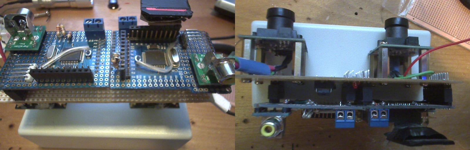
Nothing is moving yet... no gears or chains, but I have finally found a hobby shop that has some good stuff.· there is no hand-control board, with a menu system, either.· The jumper wires you see in the photo were only required because I didn't want to tear it all apart, solder everything and then tear it apart again to start the next iteration.·
This project requires both a video projector and a monitor... but for reasons beyond the scope, I have found myself switching which video goes to which display... so, a video switcher is also required.
When I came across the Gigaware Micro Projector, I stopped developing the current hardware version...· since I·can now build the projector· right into· the camera.· The current camera has a slight amount of convergence... owing to a slight bowing in the board...which· resulted from cramming the board into the jig.· That issue was what originally inspired me to write the calibration routine... so that I could actually measure the convergence.·
The current hardware does allow me to swing the sensors by 90 degrees... but not to make small·adjustments of the angle... so, that has to be fixed.· The calibration routine will allow me to put a servo on the vertical· axis of each camera and map out the exact convergence angles for each servo setting.
The calibration step currently requires physical measurements...such as·the distance from the camera to the wall... which if done correctly, would require a plumb line for each set of measurements.· Since I am going to be using Pingers anyway... the next version will also incorporate a Ping ultrasonic distance sensor.
Keeping the camera on the· level· in actual use is going to be an issue... so the next version will also use a Memsic accelerometer to measure the various title angles...is necessary for both calibration and for the future bot to use to level itself.·
Finally, I am going to· mate the TSL unit to a pair of higher resolution· cameras...
and use the TSL both for photogrammetry and also to control the other camera.
One step at a time (of course[noparse]:)[/noparse]
ILMP
Rich
Post Edited (rjo_) : 4/13/2010 6:44:20 PM GMT
Rather than tearing down the camera and rebuilding it, I decided to see what it could do.· Being mechanically challenged... my options were somewhat limited.· After a couple of misdirections, I settled upon building the camera into a cabinet and then building a very simple one axis table, using drawer slides from Home Hardware.·
For motion, I used a carriage mechanism from an old IBM typewriter.· The stepper motor is 7.5deg· 4.8Ohm.· Power comes from a RadioShack 2.5A variable power supply, set at 7.5V.· The images below were acquired using half stepping.· Original image data was saved to SD as 3 (1200K) images (r,g, and b) at a resolution of 256 (16 bit) pixels per line.· Half stepping produced 2400 lines of true data.· The 3 files were then combine in ImageJ The aspect ratio was adjusted in ImageJ using linear interpolation, with horizontal magnification of 19x.· Finally the 36M files were compressed using 24 bit JPEG.·
Color was produced by illuminating sequentially using red, green and blue LEDs.· I used the 4 pin high output rectangular LEDs from RadioShack, mostly because they conveniently operate at 3.3V and the ratio of light output can be calculated from the package info.· I used 4 green, 6 blue and 1 red led.
This isn't exactly correct... and could be corrected by adjusting the exposure parameter for each channel.
So... the data starts out as 12 bits per channel... this is stored as word sized data in three 1200 K files... which is then combined into a single 8 bits per channel jpgs.··
The idea is to produce a 3D scanner... so we are just one step away!
Rich